Sliding levered handles engaging and pushing memory modules into extender-card socket
Active Publication Date: 2006-01-03
KINGSTON DIGITAL CO LTD
12 Cites 25 Cited by
AI-Extracted Technical Summary
Problems solved by technology
However, cables and components 28 may crowd around memory module socket 18, making it difficult to insert memory module 10.
While module insertion is performed rarely in an end-user PC, when motherboard 26 is used to test memory modules, such restricted access is problematic.
While insertion force may be significant, the ...
Abstract
A levered handle has an elongated slot that allows the levered handle to both slide and pivot over a pivot axis. The levered handle is slid over the pivot axis to allow a notch engager to engage a notch on a memory module. Then the notch engager is forced downward as the levered handle pivots upward about the pivot axis, causing a downward force to be applied to the notch on the memory module. This forces the memory module into a memory module socket. The memory module socket requires a reduced insertion force because the notch engager on the levered handle engages the notch on the memory module and applies downward pressure. A levered handle without the elongated slot can slide along the pivot axis perpendicular to the memory module to engage the notch. Both ejection and insertion forces can be reduced.
Application Domain
Engagement/disengagement of coupling parts
Technology Topic
Memory moduleEngineering +1
Image
Examples
- Experimental program(1)
Example
[0029]The present invention relates to an improvement in memory module sockets. The following description is presented to enable one of ordinary skill in the art to make and use the invention as provided in the context of a particular application and its requirements. Various modifications to the preferred embodiment will be apparent to those with skill in the art, and the general principles defined herein may be applied to other embodiments. Therefore, the present invention is not intended to be limited to the particular embodiments shown and described, but is to be accorded the widest scope consistent with the principles and novel features herein disclosed.
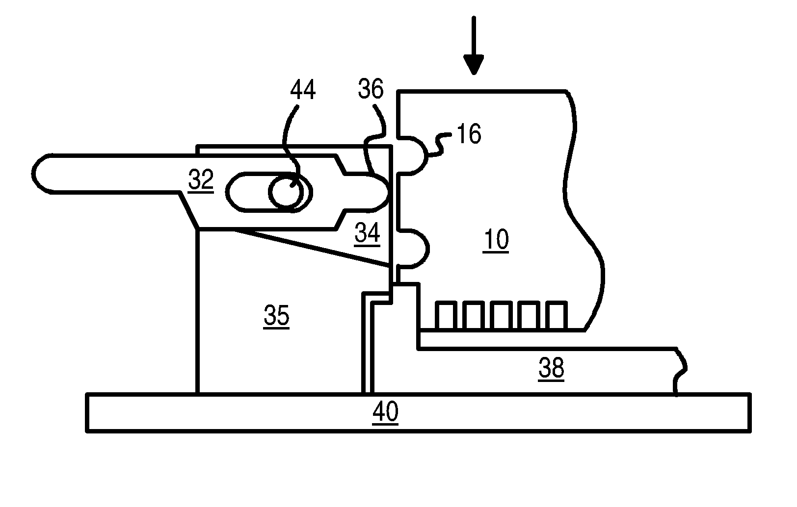
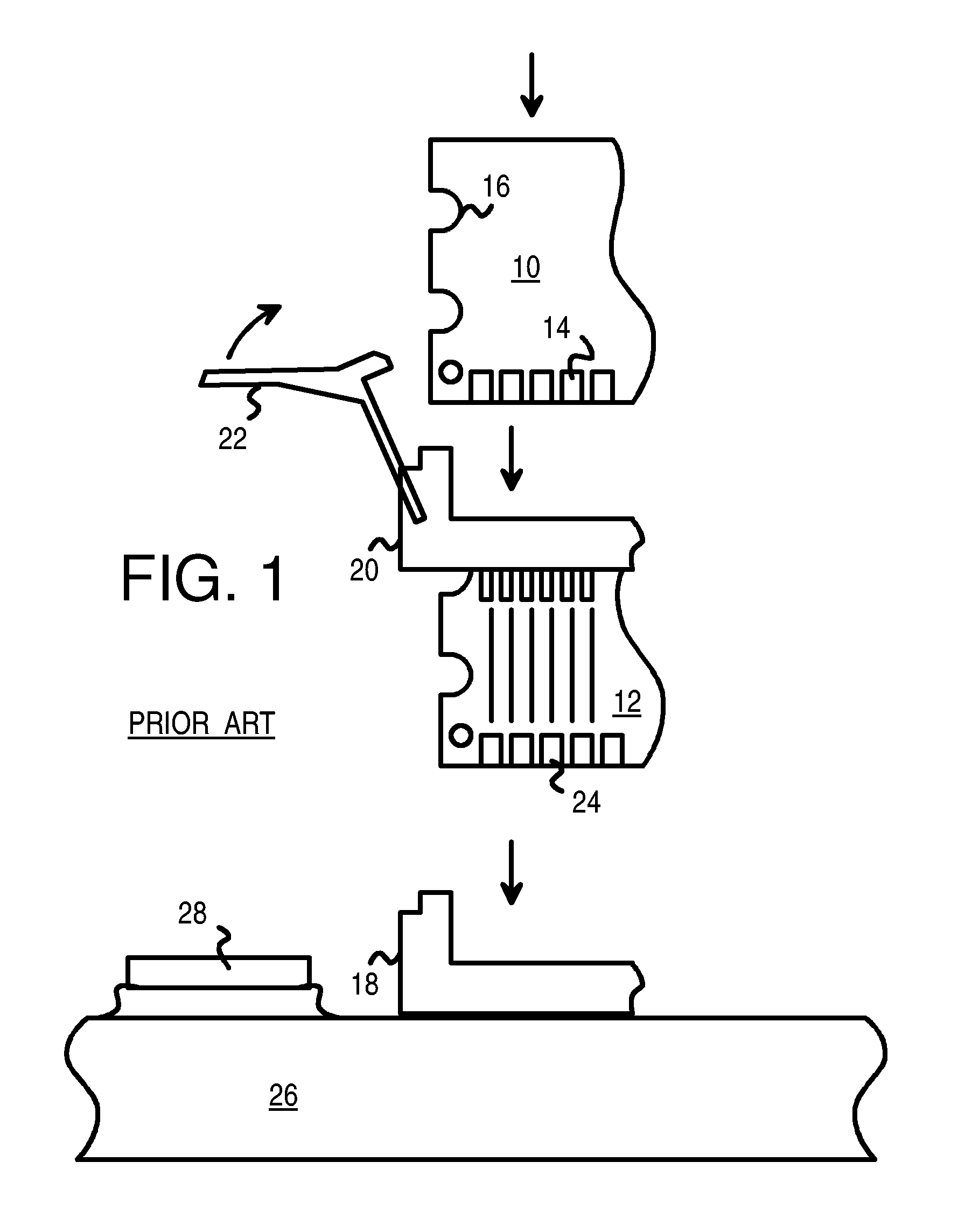
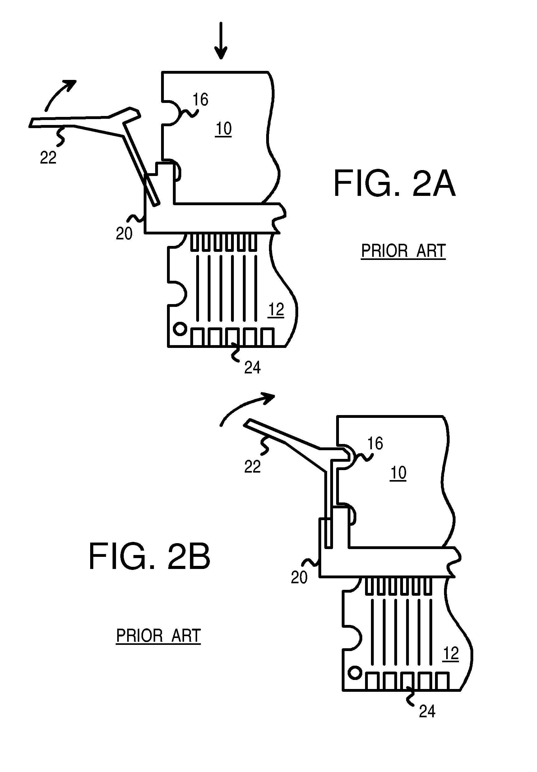
[0030]The parent application disclosed using leverage to increase the user's force on a memory module during insertion. Rather than simply retaining the memory module in the socket after insertion, as retention clips do, levered handles apply downward force on a memory module before it is fully inserted. Thus insertion of memory modules into sockets is eased.
[0031]The inventors have further realized that the pivot of the levered handles may be a slidable pivot rather than a fixed pivot. The levered handle may slide along the pivot point, further aiding engagement of the notch engager with the notch on the memory module. In particular, the levered handle may slide along the pivot as the user inserts the notch engager into or out of the notch. The levered handle then pivots about the pivot axis without sliding to apply the insertion force.
[0032]FIGS. 4A–C illustrate operation of a sliding leveraged handle to apply an insertion force on a memory module being inserted into a memory module socket. In FIG. 4A, memory module 10 is partially inserted by a user into a slot opening in memory module socket 38. Guides along the sides of memory module socket 38 may guide memory module 10 into position.
[0033]Mount 34 is fixed relative to memory module socket 38 and has pivot axis 44 which is also fixed relative to mount 34. However, levered handle 32 has an elongated slot that fits over pivot axis 44, allowing levered handle 32 to slide along pivot axis 44.
[0034]In FIG. 4A, levered handle 32 has been pulled out, away from memory module 10, and has slid along pivot axis 44 so that levered handle 32 is in the fully opened position.
[0035]Notch engager 36 is formed on levered handle 32 and is initially slid away from memory module 10 being inserted into memory module socket 38. During insertion, memory module 10 is pushed into memory module socket 38 by a user so that notch 16 on memory module 10 is opposite notch engager 36 and at about the same level. As shown in FIG. 4A, memory module 10 has not yet be inserted this far.
[0036]With memory module 10 inserted a proper amount into memory module socket 38, notch 16 aligns with notch engager 36 when levered handle 32 is slid inward along pivot axis 44. If notch 16 on memory module 10 is too high relative to notch engager 36, then the user can push memory module 10 farther down into memory module socket 38 until notch 16 aligns with notch engager 36.
[0037]The handle side of levered handle 32, opposite from notch engager 36, can be longer or heavier so that the handle side of levered handle 32 naturally rests on a flat landing portion of handle aligner 35, which is part of mount 34. Thus the position of levered handle 32 shown in FIG. 4A is known as the rest position.
[0038]In FIG. 4B, levered handle 32 is slid toward memory module 10 by the user. The elongated slot on levered handle 32 allows levered handle 32 to slide along pivot axis 44. Notch engager 36 fits into notch 16 on memory module 10 as levered handle 32 is slid inward toward memory module 10.
[0039]In FIG. 4C, levered handle 32 is pivoted upward around its pivot point, axis 44 on mount 34. The far end of levered handle 32 if lifted by the user, causing notch engager 36, on the opposite side of the fulcrum of pivot axis 44, to be moved downward.
[0040]The bottom of notch engager 36 begins to push against the bottom of notch 16 as levered handle 32 is lifted. As levered handle 32 is rotated further, memory module 10 is forced downward, farther into memory module socket 38.
[0041]After levered handle 32 has been rotated the full amount, memory module 10 is fully inserted into memory module socket 38. Good electrical contact is made between the metal contacts on memory module 10 and those in memory module socket 38.
[0042]While the amount of downward movement of memory module 10 as levered handle 32 is rotated may appear to be small, as shown by comparing the locations of memory module 10 in FIGS. 4B and 4C, this portion of module insertion often required the greatest force as the metal contacts rub together and make their tightest fit. Thus the user is spared from direct application of the greatest force by use of levered handle 32. Due to its leveraging ability, levered handle 32 multiplies the force applied by the user, resulting in a greater force applied to memory module 10 by notch engager 36 than the user applies to the end of levered handle 32. Of course, should the user hold levered handle 32 in the middle of its arm, rather than the far end, the amount of leverage is reduced, and the user must apply greater force.
[0043]While levered handle 32, notch engager 36, and mount 34 may be part of or mounted next to a standard memory module socket, such as a socket on a PC motherboard, one embodiment uses them as part of a test adapter board. FIG. 5 shows a test adapter board with an extender card and a sliding levered handle for aiding insertion of memory modules.
[0044]Levered handle 32, shown in its open position, is slid along pivot axis 44 toward memory module 10, causing notch engager 36 to engage notch 16 in memory module 10 when memory module 10 is inserted a proper, partial amount into memory module socket 38. As levered handle 32 is lifted upward by a user to rotate about pivot axis 44 on mount 34, the force exerted by notch engager 36 onto notch 16 forces memory module 10 downward so that metal contacts 14 mate with contacts inside memory module socket 38.
[0045]Only the left end of memory module socket 38 is shown. Another slidable levered handle 32 mounted to another mount 34 are on the right end of memory module socket 38 and apply force on that right end of memory module 10 in a similar fashion. These right-side elements are not shown, but can be seen in FIG. 7.
[0046]Mount 34 and handle aligner 35 are mounted to base board 40, which can be attached above motherboard 26 by several standoffs 48. Screw or bolt 49 can fit through a hole in base board 40, through a hollow center of standoff 48, and through another hole in motherboard 26. Other kinds of board attachments can be substituted for standoffs 48.
[0047]Standoffs 48 and the height of extender card 12 can be made tall enough to allow for sufficient clearance or space between base board 40 and motherboard 26 so that components 28 have enough air flow for cooling.
[0048]Memory module socket 38 is part of extender card 12, being attached to an upper edge of extender card 12. The lower edge of extender card 12 has metal contacts 24, which fit inside memory module socket 18 on motherboard 26. Extender card 12 fits in opening 46 in base board 40. Opening 46 is wider than extender card 12, but not as wide as memory module socket 38, allowing the ends of memory module socket 38 to rest on the upper surface of base board 40 around opening 46.
[0049]A bar or protrusion extending from handle aligner 35 on mount 34 can fit in a notch on the ends of memory module socket 38 as shown, to hold memory module socket 38 down on the top surface of base board 40. Memory module socket 38 and extender card 12 can be held firmly in place to base board 40, which can then be lowered into position over motherboard 26, as metal contacts 24 of extender card 12 are fitted into memory module socket 18.
[0050]FIGS. 6A–B show operation of the levered handle on a test adapter board. Base board 40 is shown mounted to motherboard 26 by standoffs 48 and bolt 49. Three, four, or more of such standoffs 48 may be used, preferably using existing holes on motherboard 26. Levered handle 32 operates as described before, sliding along pivot axis 44 causing notch engager 36 to engage notch 16. As levered handle 32 is rotated around pivot axis 44, notch engager 36 applies downward force on memory module 10, forcing it into memory module socket 38. In FIG. 6A memory module 10 is fully inserted.
[0051]During ejection, FIG. 6B, the user pushes down on the end of levered handle 32, causing it to rotate about pivot axis 44. Notch engager 36 pulls upward on notch 16. As levered handle 32 is pushed downward, notch engager 36 applies an upward force on the bottom edge of notch 16 on memory module 10. Memory module 10 is forced out of memory module socket 38 by a slight amount. Since the greatest ejection force is often the initial movement of memory module 10, this initial ejection reduces the force required of the user to pull memory module 10 completely out of memory module socket 38. The user then slides levered handle 32 outward along pivot axis 44 to disengage notch engager 36 from notch 16. Memory module 10 can then be fully removed by the user.
[0052]Levered handle 32, which applies an insertion force through notch engager 36, reduces the force the user applies to memory module 10. This can reduce the possibility of injuries to the user, such as repetitive-stress injuries.
[0053]Sliding levered handle 32 along pivot axis 44 allows notch engager 36 to be better and more fully and securely inserted into notch 16. The better fit of notch engager 36 into notch 16 prevents levered handle 32 from dislodging or disengaging from memory module 10 as levered handle 32 is rotated around pivot axis 44. This results in more reliable operation. Subsequently, a single levered handle 32 can be used for both insertion and ejection of memory module 10.
[0054]FIG. 7 is a perspective view of a motherboard tester with the test adaptor board with sliding levered handles to ease insertion of memory modules. Test programs that test memory can be executed on motherboard 26, such as memory tests during boot-up or more extensive tests run after initialization. A memory module is normally inserted into memory module socket 18 in a standard PC, but instead extender card 12 is inserted into memory module socket 18. The top of extender card 12 has memory module socket 38 that receives memory module 10 for testing.
[0055]More than one memory module 10 may be tested at a time. A second extender card 12 with a second memory module socket 38 can also be supported by base board 40. Two pairs of levered handles 32 can be fitted on mounts 34, each pair engaging a notch 16 on a different memory module 10 being inserted into a different memory module socket 38. In another embodiment, each levered handle 32 can engage two memory modules 10, with two memory module sockets 38 for each pair of levered handles 32. One opening 46 can have four extender cards 12, or two or more separate openings 46 may be used.
[0056]The elongated slot on levered handle 32 that fits over pivot axis 44 may be hidden by the sides of mount 34 as shown when mount 34 surrounds pivot axis 44 and levered handle 32 on the sides.
[0057]Ribs 72 may be formed on base board 40. Ribs 72 may fit inside a heater cover (not shown) that can be placed over memory modules 10 when inserted into memory module sockets 38. The heater cover and base board 40 form a heat chamber that allows memory modules 10 to be heated and tested at an elevated temperature. The heater cover could also be attached to base board 40 by a hinge.
[0058]FIGS. 8A–B show an alternate embodiment of the sliding levered handles that slide in a perpendicular direction. Rather than sliding the levered handle horizontally toward the memory module, the sliding motion may be in other directions. In this embodiment, the levered handle is slid in a perpendicular direction to the plane of the memory module to engage the notch.
[0059]FIG. 8A is an overhead view with memory module 10 edge-on as it is being inserted into memory module socket 38. Levered handle 50 is not in the same plane as memory module 10 but is offset. Levered handle 50 pivots about pivot axis 44, which is a rod attached to mount 58.
[0060]Levered handle 50 can slide along pivot axis 44 as shown by the arrow in FIG. 8A. Sliding ring 56 is fixedly attached to levered handle 50 but slides along pivot axis 44. Levered handle 50 can slid along pivot axis 44 to open position 62, and to engaged position 60. Portions of mount 58 act as stoppers 52, restricting movement past positions 60, 62 by limiting movement of sliding ring 56.
[0061]When levered handle 50 is in open position 62, conical notch engager 64 is outside of notch 16. As levered handle 50 is slid along pivot axis 44 to engaged position 60, conical notch engager 64 slides into notch 16 to engage the memory module notch.
[0062]FIG. 8B is a front view. Conical notch engager 64 is engaged with notch 16 of memory module 10. Levered handle 50 rotates around pivot axis 44 along with sliding ring 56. Rotating stop 68 is a protrusion of sliding ring 56 on levered handle 50 that is stopped by base stop 70, which stops excess rotation of levered handle 50 once memory module 10 has been lifted out of memory module socket 38.
[0063]FIG. 9 shows rotation of the levered handle during insertion of a memory module. Levered handle 50 is fixed to sliding ring 56 which are slid toward the plane of the drawing page to engage conical notch engager 64 into notch 16 of memory module 10. The user then pulls upward on the end of levered handle 50 in position 50′, causing it and sliding ring 56 to rotate about pivot axis 44. This rotation upward on the handle end of levered handle 50 causes a downward force on the opposite end of the fulcrum, pivot axis 44. This downward force is applied to conical notch engager 64 by levered handle 50 and thru conical notch engager 64 to notch 16, causing memory module 10 to be pushed downward into memory module socket 38.
[0064]In the initial position 50′, rotating stop 68 touches a step in base stop 70, which holds levered handle 50 in the initial position as the user first aligns and partially inserts memory module 10 into memory module socket 38. For removal of memory module 10, the user pushes downward on the end of levered handle 50, causing an upward force to be applied by conical notch engager 64 on notch 16, ejecting memory module 10 slightly from memory module socket 38. Further rotation of levered handle 50 can be stopped by rotating stop 68 contacting base stop 70.
[0065]FIG. 10 is another embodiment with a different rotating stop. The exact location of rotating stop 68 may be shifted to a variety of locations, such as the example shown in FIG. 10. The location of the step on base stop 70 can be adjusted so that a desired amount of rotation of levered handle 50 occurs before being stopped. Base stop 70 can be a part of mount 58.
ALTERNATE EMBODIMENTS
[0066]Several other embodiments are contemplated by the inventors. For example mount 58 and base stop 70 may be molded together or may be separate and can have a variety of shapes and forms. Base board 40 may have a variety of shapes and have various cutouts and openings 46 to fit extender cards 12 and components on motherboard 26 that protrude above base board 40. Base board 40 may be made from a thicker, more insulating material or fiberglass to improve the heat chamber.
[0067]While engagement of notch engager 36 or conical notch engager 64 with an upper notch 16 of memory module 10 has been shown, engagement with a lower notch or other feature of a memory module could occur with an appropriate position and design of levered handle 32, axis 44, and notch engager 36. Rotations of different amounts such as 10, 30 or 45 degrees can be designed for by changes to levered handle 32, mount 34, notch engager 36, and their positions relative to notch 16 and memory module socket 38. The length or levered moment arm of levered handle 32 or 50 may be increased or decreased, changing the leverage efficiency.
[0068]Rotating stop 68 and base stop 70 may not be necessary in some embodiments. Levered handle 50 may remain in the initial open position without a stop. The initial, open position of levered handle 50 may not be exactly aligned with notch 16, but may be at an angle, such as a slight upward angle, increasing the rotational movement during insertion. The angle to notch 16 may be allowed to vary, allowing the user to partially insert memory module 10 into memory module socket 38 by varying amounts.
[0069]More than one memory module socket may be used on base board 40. Each levered handle 32 could engage just one notch on one memory module, or notch engager 36 could have an elongated depth (the direction normal to the plane of FIG. 5) so that notches on two or more memory modules could be engaged simultaneously. Several levered handles 32 could also be ganged together so that multiple memory modules are acted upon at the same time.
[0070]Various other enhancements can be made, such as locks, stops, bumps, ridges, or holding mechanisms for holding levered handle 32 in its various positions. The levered handles could be attached to a base that is attached directly to a memory module socket, without using a base board 40. The levered handles have application in non-tenting environments as well, such as on consumer PC motherboards.
[0071]Positions such as up, down, etc. are relative and may be interchangeable, such as when the socket is transformed or re-positioned. The levered handle can be made from a variety of materials such as metal or rigid plastic. The notch engager and other components can be integral with the levered handle or attached to the levered handle.
[0072]A bar portion of handle aligner 35 (see FIG. 5) may be used to hold down memory module socket 38, or a screw (not shown) horizontally through mount 34 can attach to the side of memory module socket 38 to hold memory module socket 38 and extender card 12 in place on base board 40 or on a motherboard. Memory module socket 38 could be mounted to base board 40 or to mount 34 in a variety of other ways, such as by adhesive, clamps, screws or bolts in various locations, etc. The shape and size of opening 46 can vary, such as one or more long rectangles or ovals to closely fit one or more extender cards 12, or other shapes.
[0073]The handle aligner could have many shapes and forms and could be deleted. The handle aligner may be separate from mount 34 or may be a part of mount 34 or mount 58. Various ridges, stops, grooves, etc. could perform the function of stopping movement of levered handle 32 or 50 when the memory module is fully inserted, or of holding levered handle 32 or 50 in the open position or in some other position. Sliding ring 56 may be part of levered handle 50 and may have shapes other than ring shapes. Sliding ring 56 may simply be a center portion of levered handle 50 around a hold for the pivot axis.
[0074]An ejector foot may be added as described in the parent application. The ejector foot may be pushed downward by the bottom edge of memory module 10 when fully inserted, causing the ejector arm to be in the upright position shown in FIG. 6A of the parent application. The ejector foot and ejector arm are on opposite sides of an ejector pivot, which can be an axis such as a bolt, as can axis 44 of levered handle 32.
[0075]The ejector could be pushed by levered handle 32 or could be attached to levered handle 32. Conical notch engager 64 could have shapes other than conical, such as being a cylinder, a semi-sphere, or a point. The conical shape may be only part of a full cone, such as half of a cone. A rod may be used for pivot axis 44, or some other shape may be used.
[0076]Any advantages and benefits described may not apply to all embodiments of the invention. When the word “means” is recited in a claim element, Applicant intends for the claim element to fall under 35 USC Sect. 112, paragraph 6. Often a label of one or more words precedes the word “means”. The word or words preceding the word “means” is a label intended to ease referencing of claims elements and is not intended to convey a structural limitation. Such means-plus-function claims are intended to cover not only the structures described herein for performing the function and their structural equivalents, but also equivalent structures. For example, although a nail and a screw have different structures, they are equivalent structures since they both perform the function of fastening. Claims that do not use the word “means” are not intended to fall under 35 USC Sect. 112, paragraph 6. Signals are typically electronic signals, but may be optical signals such as can be carried over a fiber optic line.
[0077]The foregoing description of the embodiments of the invention has been presented for the purposes of illustration and description. It is not intended to be exhaustive or to limit the invention to the precise form disclosed. Many modifications and variations are possible in light of the above teaching. It is intended that the scope of the invention be limited not by this detailed description, but rather by the claims appended hereto.
PUM


Description & Claims & Application Information
We can also present the details of the Description, Claims and Application information to help users get a comprehensive understanding of the technical details of the patent, such as background art, summary of invention, brief description of drawings, description of embodiments, and other original content. On the other hand, users can also determine the specific scope of protection of the technology through the list of claims; as well as understand the changes in the life cycle of the technology with the presentation of the patent timeline. Login to view more.