Structure for electrode terminals of battery module

a battery module and structure technology, applied in the direction of cell components, sustainable manufacturing/processing, final product manufacturing, etc., can solve the problems of electrode terminal b, short circuit, and complicated connection structure,

a battery module and structure technology, applied in the direction of cell components, sustainable manufacturing/processing, final product manufacturing, etc., can solve the problems of electrode terminal b, short circuit, and complicated connection structure,

US6982131B1Inactive Publication Date: 2006-01-03PANASONIC CORP +1

Image

  • Structure for electrode terminals of battery module
  • Structure for electrode terminals of battery module
  • Structure for electrode terminals of battery module

Examples


case 3

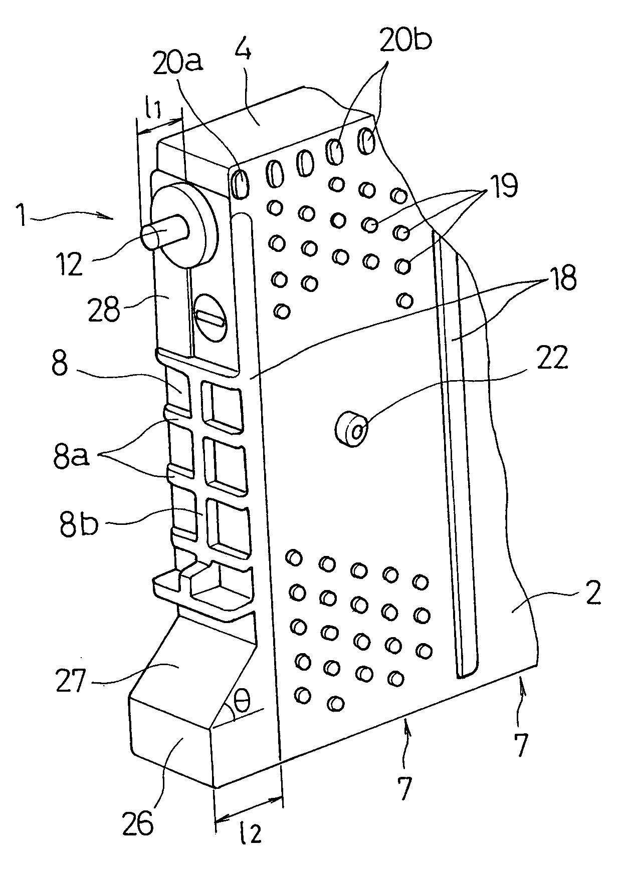
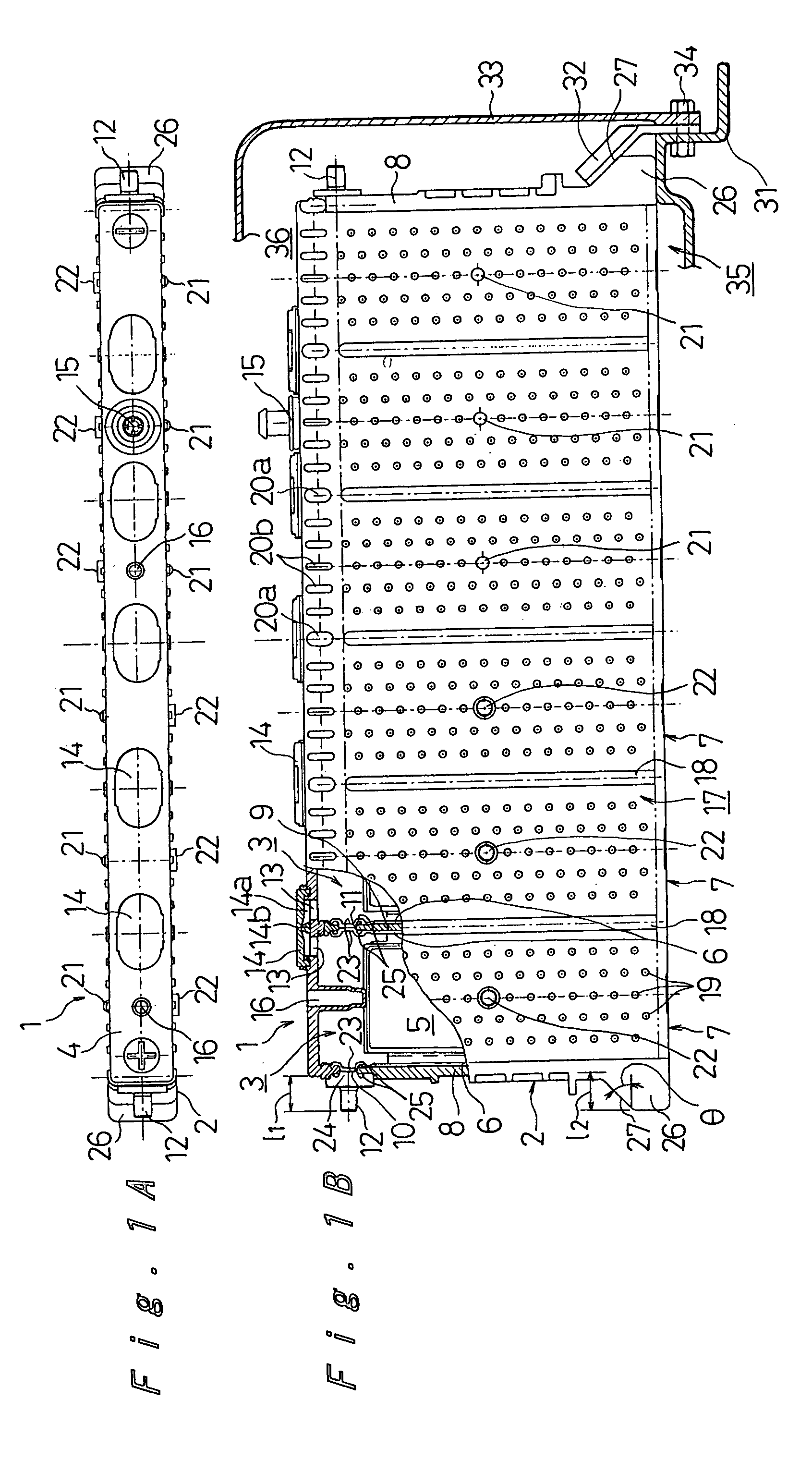
[0029]Each cell case 3 contains an electrode plate group 5, comprising numerous positive and negative electrode plates that are parallel to the long-side surfaces of the cell case 3 and that are stacked in the short-side direction with separators between them, and collector plates 6 that are joined to both ends of this electrode plate group 5. The result is a cell 7.

[0030]Each electrode plate group 5 comprises numerous positive electrode plates and numerous negative electrode plates disposed in alternating fashion, and each positive electrode plate is covered with a sheath-like separator having openings in the lateral direction. The lateral edges of the group of positive electrode plates protrude beyond the group of negative electrode plates on one side, and the lateral edges of the group of negative electrode plates protrude beyond the group of positive electrode plates on the opposite side, and these protruding lateral portions form the lead portions, to the lateral ends of which ...


PUM

PropertyMeasurementUnit
angle of inclinationaaaaaaaaaa

Abstract

On the opposite end walls of a flat, prismatic battery case of a battery module where electrode terminals are attached, protruding components are formed such as to protrude further than the electrode terminals. Terminal holes are formed in the end walls in which the electrode terminals are fitted, and the thickness of the end walls of the integral battery case in the vicinity of the terminal holes is not the same on both sides of each of the terminal holes. Also, one or a plurality of vertical and horizontal ribs are formed on the end walls between the electrode terminals and the protruding components. Further, a sealing structure is included for a battery.

Description

[0001]The present application is a continuation-in-part of prior application Ser. No. 29 / 119,908, filed Mar. 10, 2000, now U.S. Pat. No. D437,287 S, issued Feb. 6, 2001.BACKGROUND OF THE INVENTION[0002]The present invention relates to a prismatic rechargeable battery module in which electrode plates and electrolyte are contained and sealed in a prismatic battery case, and electrode terminals are provided protruding from both ends of this prismatic battery case in the longitudinal direction. More particularly, the present invention relates to an improved structure for the electrode terminals of such rechargeable battery module.[0003]Because of their excellent energy density, nickel metal hydride batteries and other such alkaline rechargeable batteries have in recent years come to be utilized as the power source for electric automobiles, for example. In an effort to obtain a large output while preserving a compact size, a sealed prismatic rechargeable battery has been proposed in Japa...

Claims


Application Information

Patent Timeline
03 Jan 2006
Publication
US6982131B1
IPC
H01M2/02; H01M2/06; H01M10/04; H01M10/28; H01M10/34; H01M50/112; H01M50/505; H01M50/529; H01M50/55; H01M50/567
CPC
H01M2/0237; H01M2/0242; H01M2/0245; H01M2/1077; H01M2/305; H01M10/281; H01M2/1083; H01M2/0217
Inventors
HAMADA, SHINJI; YAMAMURA, IZUMI