Particle detection by electron multiplication

a technology of electron multiplication and particle detection, applied in the field of particle detection, can solve the problems of mismatch between the desired sensitive input area and add confusion in the interpretation of the spectrum

Active Publication Date: 2006-01-03
ETP ION DETECT PTY LTD
View PDF18 Cites 21 Cited by
  • Summary
  • Abstract
  • Description
  • Claims
  • Application Information

AI Technical Summary

Benefits of technology

[0014]The present invention proposes three mechanisms for achieving the just-mentioned objective that may each be employed alone, in conjunction in the same electron deflection, or sequentially. Each mechanism takes advantage of the secondary electrons that result from the impact of energetic electrons or ions against a surface. A surface able to function in this way is hereinafter referred to as a dynode. Each mechanism involves deflection of electrons by an electrostatic field in conjunction with a magnetic field preferably generally orthogonal or nearly orthogonal to the electrostatic field, in contrast to the typical environment of most commercial electron multipliers in which deflection is by electrostatic field only.

Problems solved by technology

This requirement often results in a mis-match between the desired sensitive input area and the sensitive area of the amplifying section of the electron multiplier (which can be much smaller).
Such artefacts are usually seen as unwanted small peaks in the mass spectrum, which are not coincident with the primary signal associated with the incoming ion, and thus add confusion when interpreting the spectrum.

Method used


Image

  • Particle detection by electron multiplication
  • Particle detection by electron multiplication

Examples


Embodiment Construction

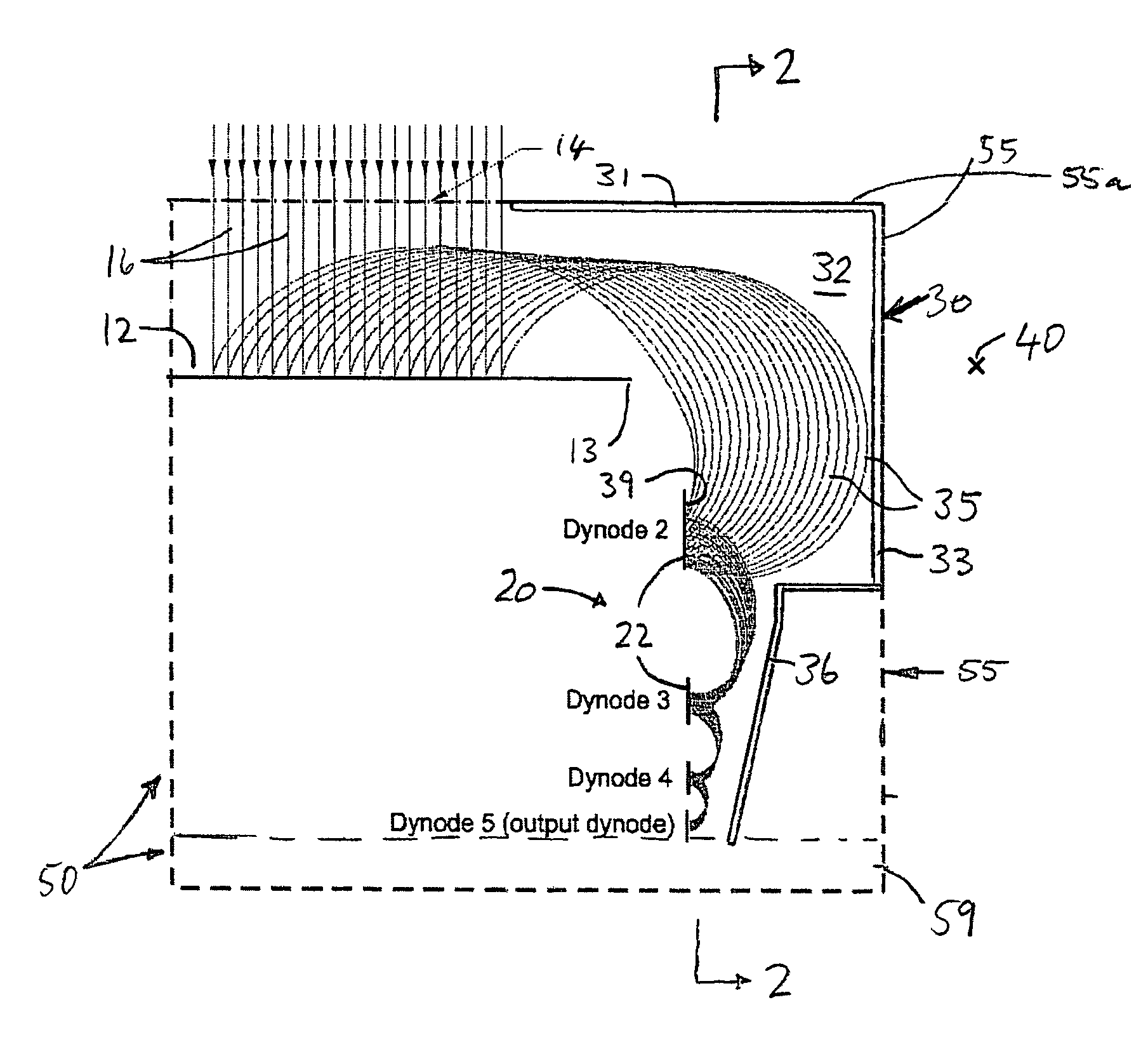
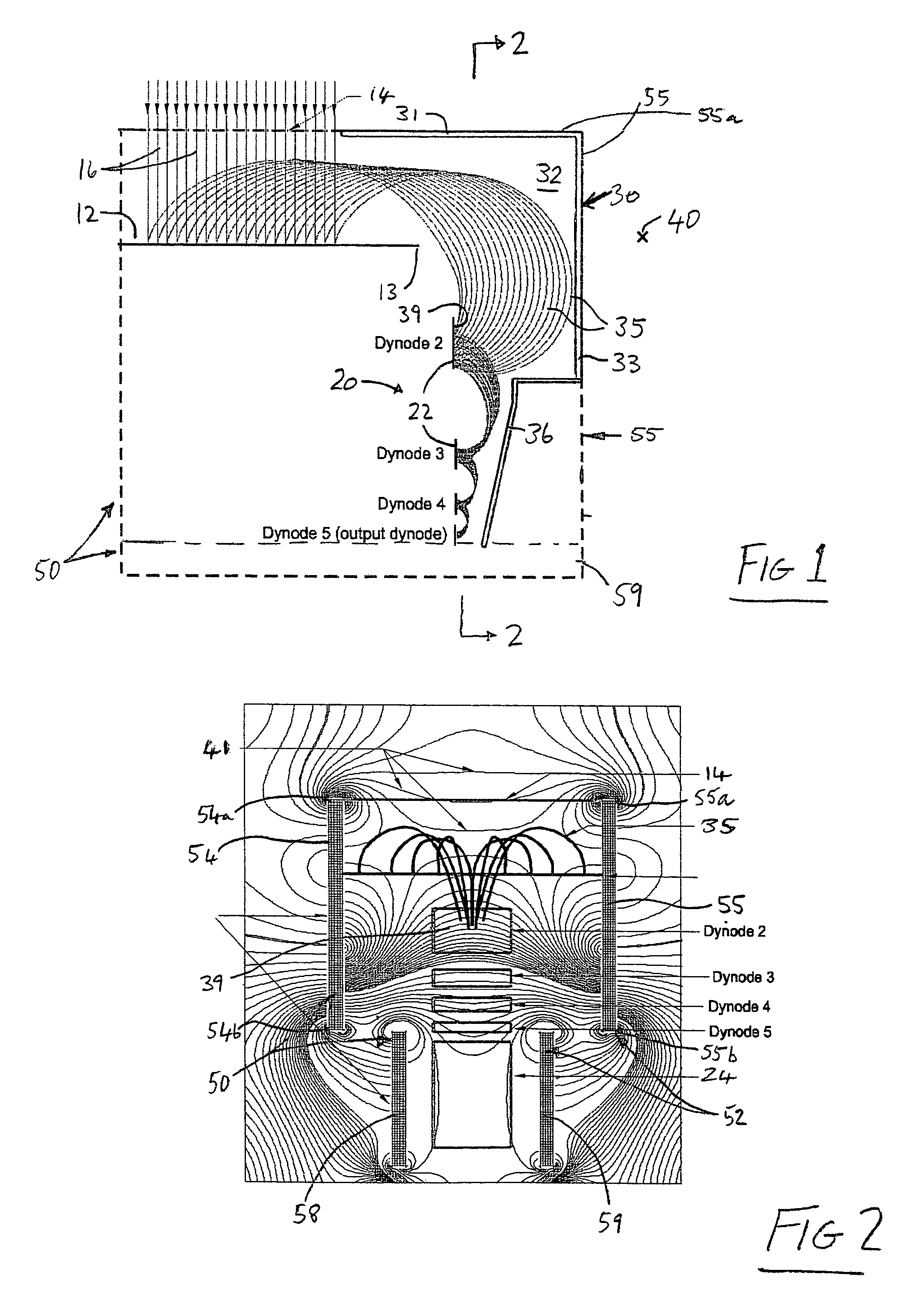
[0062]The illustrated electron multiplier 10 includes cathode means in the form of a relatively large ion impact plate 12 constituting an input dynode, designated dynode 1. Dynode 1 is disposed inwardly of an entrance grid 14 defining an input aperture. Typical input ion trajectories are indicated at 16.

[0063]A co-planar or linear array 20 of dynodes 22 extends at 90° to impact plate 12 in a direction behind and away from plate 12 relative to entrance grid 14. The plane of dynode array 20 lies slightly laterally of the adjacent edge 13 of plate 12. Dynodes 22 are designated dynodes 2, 3, 4 and 5 and are successively smaller in functional surface area. Dynodes 22 are also at a spacing from the preceding dynode that successively diminishes from dynode 2 to dynode 5. Dynode 5 is the output dynode of the focussing configuration and marks the start of the amplifying section 24 (FIG. 2).

[0064]A rectangular plate 30 is disposed as shown as an electrode for shaping an electrostatic field be...


PUM


Abstract

Electron focussing apparatus includes a cathode plate defining an impact surface on which particles impact, which surface has a finite probability of generating at least one electron for each impacting particle having predetermined characteristics. The apparatus also has an electron receiving element, and respective means for generating electrostatic and magnetic fields in a space extending from the impact surface to the electron receiving element. The means for generating the electrostatic and magnetic fields are configured whereby the E/B2 ratio adjacent the electron receiving element is smaller than adjacent the impact surface, whereby to decrease the radius of curvature of the electron trajectories adjacent the electron receiving element relative to adjacent the impact surface and to thereby focus the electron trajectories in at least one dimension. In another aspect the electron receiving element is positioned and the means for generating the electrostatic and magnetic fields are configured to cause the electrons to deflect on average through greater than 180° before impacting the electron receiving element, whereby to focus, in at least one dimension, multiple electrons generated from any given area of the impact surface to a smaller area at the electron receiving element.

Description

FIELD OF THE INVENTION[0001]This invention relates generally to the detection of particles and is concerned in particular with enhancements for this purpose of electron multiplier configurations.[0002]In the context of this specification, a “particle” may be an ion or other charged particle, a neutral particle or a photon, that is capable, when having predetermined characteristics, to cause an impacted surface to generate an electron. A common application of electron multipliers, however, is the detection of specific ions, for example in mass spectrometers, and hence for convenience particles to be detected will sometimes be referred to herein as ions.BACKGROUND ART[0003]To optimise the performance of an electron multiplier, it is often desirable to have a large sensitive input area so that particles can be detected which are incident over a large area. This requirement often results in a mis-match between the desired sensitive input area and the sensitive area of the amplifying sec...

Claims


Application Information

Patent Timeline
Patent Type & Authority Patents(United States)
IPC IPC(8): G21G5/00H01J19/82H01J25/50H01J43/04H01J49/02
CPCH01J49/025H01J43/04
Inventor STRESAU, RICHARDHUNTER, KEVINSHEILS, WAYNERAFFIN, PETERBENARI, YAIR
Owner ETP ION DETECT PTY LTD
Why Eureka
Try Eureka