Method and apparatus for a rearrangeably non-blocking switching matrix

Inactive Publication Date: 2006-01-03
CISCO TECH INC
View PDF22 Cites 253 Cited by
  • Summary
  • Abstract
  • Description
  • Claims
  • Application Information

AI Technical Summary

Benefits of technology

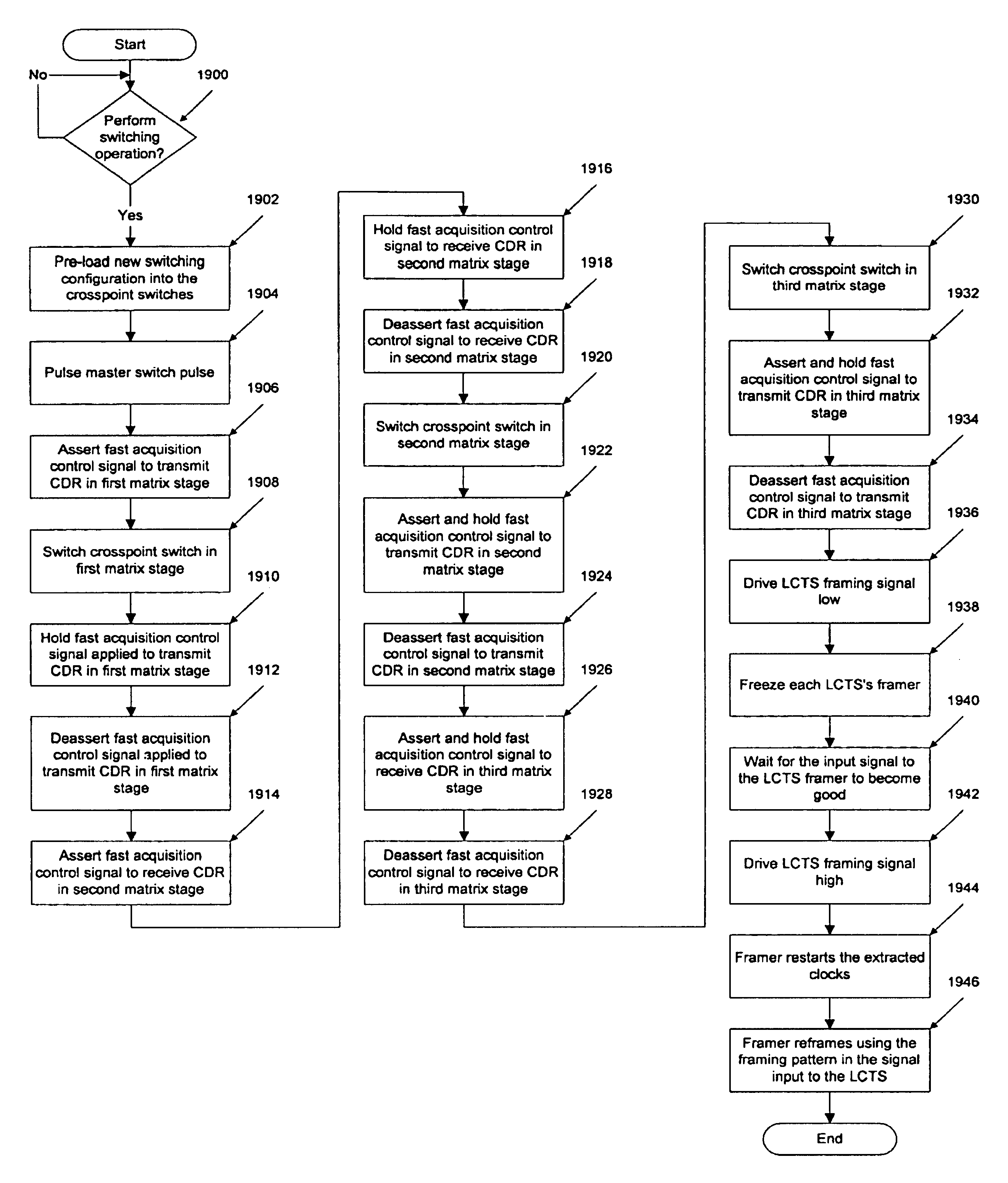
[0016]Embodiments of the present invention overcome conventional limitations by providing a switching matrix and method of operation that are relatively simple and inexpensive, but that avoid interruption of existing connections when connections are added or removed. In one embodiment, a method and apparatus according to the present invention provide a switching matrix that switches errorlessly by controlling the point in time at which switching occurs. Using such

Problems solved by technology

However, a problem with N×N crossbar switches is that such a switch grows exponentially as connections are added, meaning that N2 switches are required to build a network having N inputs and N outputs.
Because some of the paths share one or more links within the MIN, a high number of permutations cannot be routed when using such networks.
Unfortunately, information carried on some or all of the existing connections may experience errors during the switching matrix's reconfiguration.
The less “blocking” a network is,

Method used


Image

  • Method and apparatus for a rearrangeably non-blocking switching matrix
  • Method and apparatus for a rearrangeably non-blocking switching matrix
  • Method and apparatus for a rearrangeably non-blocking switching matrix

Examples


Embodiment Construction

[0051]The following is intended to provide a detailed description of an example of the invention and should not be taken to be limiting of the invention itself. Rather, any number of variations may fall within the scope of the invention which is defined in the claims following the description.

[0052]In addition, the following detailed description has been divided into sections, subsections, and so on, in order to highlight the various subsystems of the invention described herein; however, those skilled in the art will appreciate that such sections are merely for illustrative focus, and that the invention herein disclosed typically draws its support from multiple sections. Consequently, it is to be understood that the division of the detailed description into separate sections is merely done as an aid to understanding and is in no way intended to be limiting.

Introduction

[0053]A switching matrix according to the present invention is relatively simple and inexpensive, yet avoids interru...


PUM


Abstract

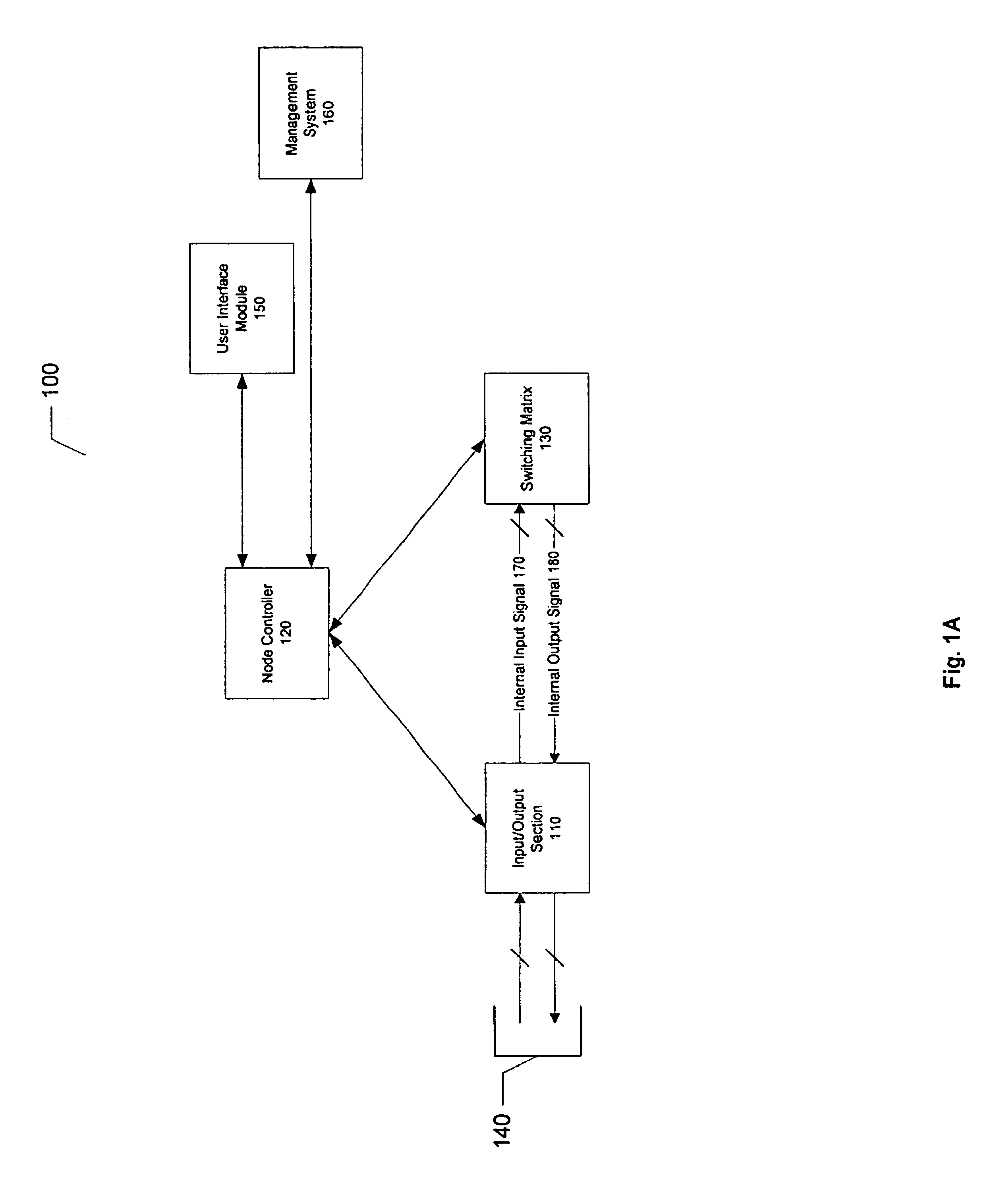
A switching apparatus is disclosed that employs a relatively simple and inexpensive switching matrix, but which avoids interruption of existing connections when connections are added or removed. The switching matrix switches errorlessly by controlling the point in time at which switching occurs. Using such a technique, switching can be performed without disturbing the connections already configured in the switching matrix, and so is referred to herein as being non-blocking. Optionally, the incoming data can be rearranged to provide a larger window of time in which the switching matrix can be switched. In the case of a switch using an optical backplane, this also allows more time for various components of the system (e.g., clock/data recovery units) to re-acquire lock. The switching apparatus includes a switching matrix and control circuitry. The switching matrix has a matrix input, a control input and a number of matrix outputs, and is configured to receive an information stream at the matrix input. The information stream includes a number of portions, while the control circuitry has a control output coupled to the control input. The control circuitry is configured to initially configure the switching matrix to output the information stream at a one of the matrix outputs and to subsequently configure the switching matrix to output the information stream at another of the matrix outputs during a period of time during which the one of the portions is transiting the switching matrix.

Description

CROSS-REFERENCES TO RELATED APPLICATIONS[0001]This application is a continuation-in-part of patent Application Ser. No. 09 / 232,395, filed Jan. 15, 1999, and entitled “A CONFIGURABLE NETWORK ROUTER,” having H. M. Zadikian, A. N. Saleh, J. C. Adler, Z. Baghdasarian, and V. Parsi as inventors. This application is hereby incorporated by reference, in its entirety and for all purposes.[0002]This application is related to patent application Ser. No. 09 / 232,397, filed Jan. 15, 1999, and entitled “A METHOD FOR ROUTING INFORMATION OVER A NETWORK,” having A. N. Saleh, H. M. Zadikian, Z. Baghdasarian, and V. Parsi as inventors; patent application Ser. No. 09 / 232,396, filed Jan. 15, 1999 and entitled “METHOD OF ALLOCATING BANDWIDTH IN AN OPTICAL NETWORK,” having H. M. Zadikian, A. Saleh, J. C. Adler, Z. Baghdasarian, and V. Parsi as inventors; patent application Ser. No. 60 / 174,323, filed herewith, and entitled “A RESOURCE MANAGEMENT PROTOCOL FOR A CONFIGURABLE NETWORK ROUTER” having H. M. Zadi...

Claims


Application Information

Patent Timeline
IPC IPC(8): H03K17/00H04L12/56H04Q11/00
CPCH04L49/1515H04Q3/52H04L49/15H04L49/30H04L49/351H04L49/201
Inventor SALEH, ALI NAJIBDUSCHATKO, DOUGLAS E.QUIBODEAUX, LANE BRYON
Owner CISCO TECH INC
Why Eureka
Try Eureka