
Linearization apparatus for linear automatic gain control in a mobile communication terminal and method for controlling the same

a technology of automatic gain control and linearization apparatus, which is applied in the direction of transmission monitoring, antennas, and electric long antennas, can solve the problems of increasing the unit cost of the inability to generally use amplifiers in the mobile communication terminal, and the high cost of good linear gain characteristics. to achieve the effect of reducing the required memory siz

Inactive Publication Date: 2006-01-03
SAMSUNG ELECTRONICS CO LTD
View PDF2 Cites 6 Cited by
  • Summary
  • Abstract
  • Description
  • Claims
  • Application Information

AI Technical Summary

Benefits of technology

The present invention provides a linearization apparatus and method for linear automatic gain control in a mobile communication terminal. The apparatus and method divide automatic gain control signals into multiple entry regions, with each region containing an initial value, resolution value, and slope character value for generating a linear automatic gain control signal. This helps to minimize the required memory size and ensure a linearity of amplification gain. The apparatus includes an initial value generator, a linearizer, and an initial value for each entry region. The method involves detecting the entry region, generating an initial value for the next region, and adding the initial value to the previous region to generate the final value. This invention helps to improve the performance and reliability of mobile communication terminals.

Problems solved by technology

However, the amplifier having a good linear gain characteristic is expensive, causing an increase in the unit cost of the mobile communication terminal.
Thus, such an amplifier is not generally used in the mobile communication terminal.
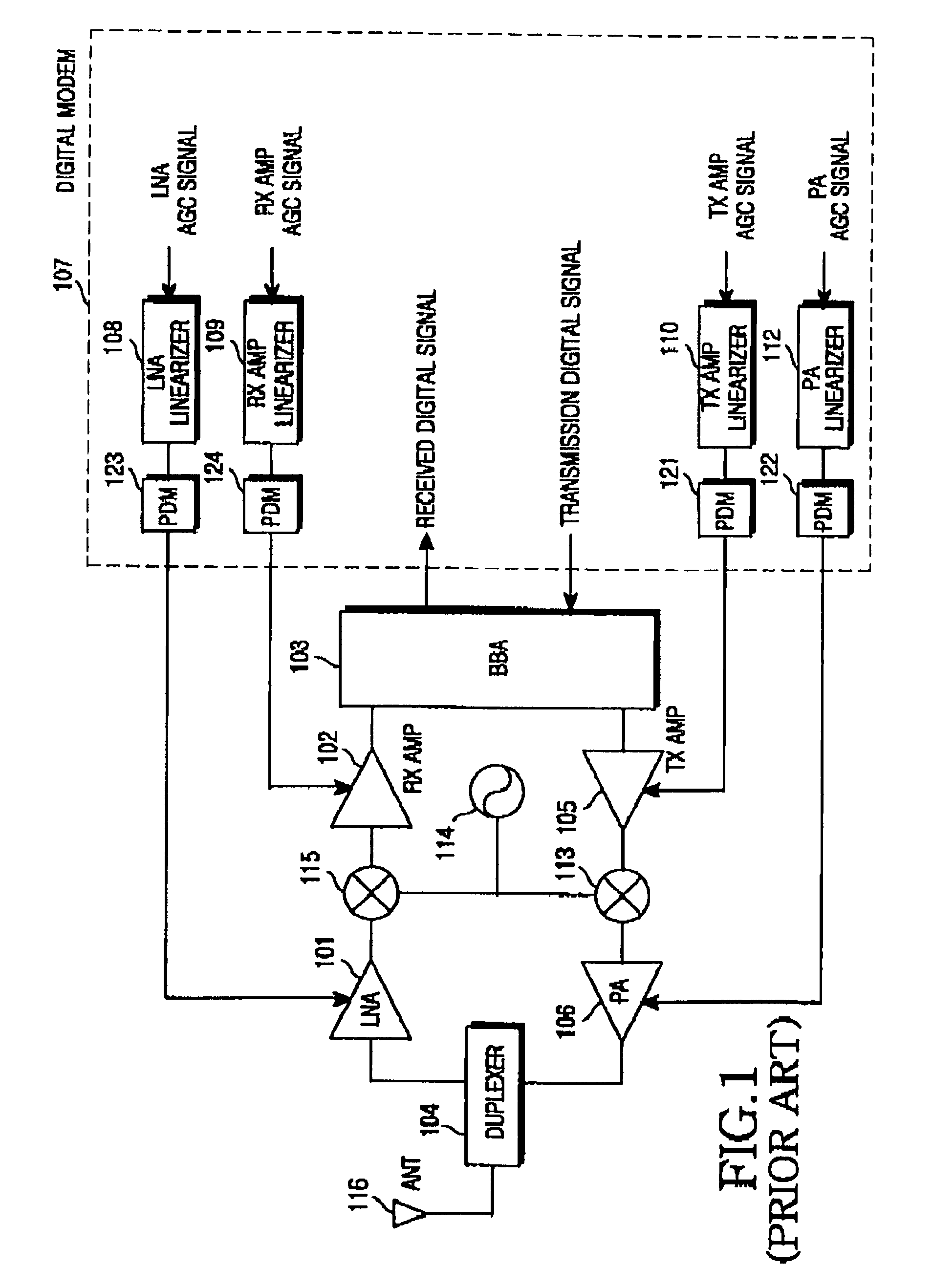
However, the power amplifier 106 also has a nonlinear gain characteristic, so it cannot linearly amplify its input signal according to an automatic gain control signal applied thereto.
However, the amplifier having a good linear gain characteristic is expensive, causing an increase in the unit cost of the mobile communication terminal.
Thus, such an amplifier is not generally used in the mobile communication terminal.
However, amplifiers having good linear gain characteristic are expensive, causing an increase in the unit cost of the mobile communication terminal.
Thus, such an amplifier is generally not used in the mobile communication terminal.
However, the amplifier having a good linear gain characteristic is expensive, causing an increase in the unit cost of the mobile communication terminal.
Thus, such an amplifier is not generally used in the mobile communication terminal.
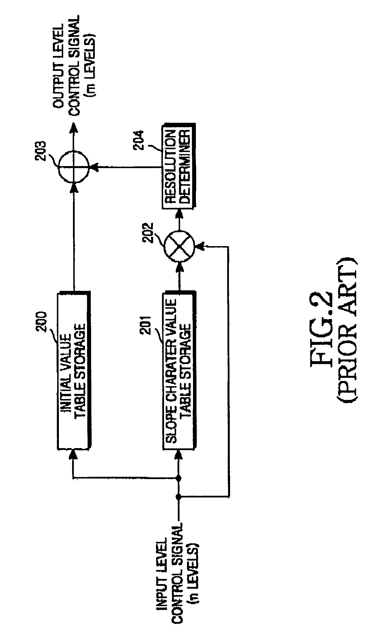
In the 3rd mobile communication system, since the standard specifications assign more channels than that of the CDMA digital mode, as many RAM tables as the number of the channels must be provided, thus causing an increase in the required size of the EEPROM.
Particularly, in the mobile communication terminal not only the EEPROM but also the RAM included in the linearization apparatus for the linear automatic gain control, increase in their size undesirably.

Method used


Image

  • Linearization apparatus for linear automatic gain control in a mobile communication terminal and method for controlling the same
  • Linearization apparatus for linear automatic gain control in a mobile communication terminal and method for controlling the same
  • Linearization apparatus for linear automatic gain control in a mobile communication terminal and method for controlling the same

Examples


Embodiment Construction

[0054]A preferred embodiment of the present invention will be described herein below with reference to the accompanying drawings. In the following description, well-known functions or constructions are not described in detail since they would obscure the invention in unnecessary detail.

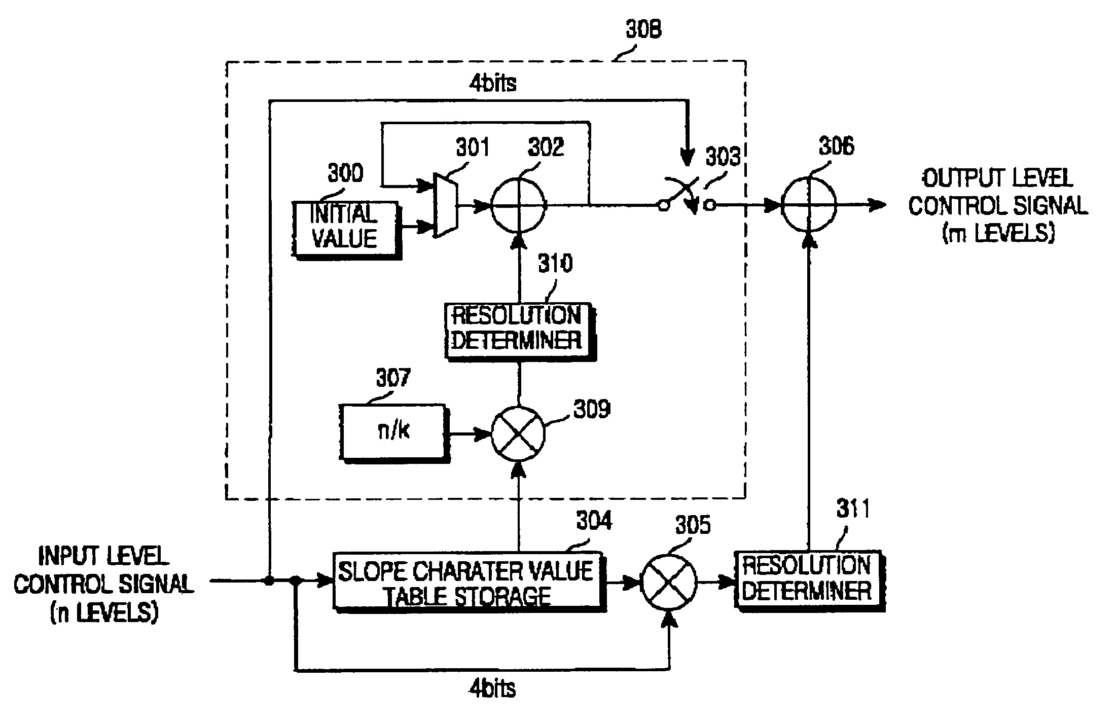
[0055]FIG. 3 is a block diagram illustrating an internal structure of a linearization apparatus for linear automatic gain control according to an embodiment of the present invention.

[0056]Before a description of FIG. 3, it should be noted that the linearization apparatus for linear automatic gain control can commonly serve as the transmission amplifier linearizer 110, the power amplifier linearizer 112, the low noise amplifier linearizer amplifier 108 and the reception amplifier linearizer 109 in the transceiver of the mobile communication terminal illustrated in FIG. 1. However, the linearization apparatus receives and generates different input level automatic control signals and output level automat...


PUM


Abstract

Disclosed is a linearization method in a mobile communication terminal wherein automatic gain control signals are divided into a plurality of entry regions, and which includes an initial value for a first entry region among the plurality of entry regions, a resolution constant and a slope character value for each entry region for generating a linear automatic gain control signal which guarantee a linearity of amplification gain of an amplifier. The linearization method comprises the steps of: detecting a corresponding entry region using a preset number of bits from the automatic gain control signal which is represented by a plurality of bits and detecting a position value of the detected entry region using the remaining bits except the preset number of bits; generating an initial value of a second entry region using the initial value of the first entry region, an entry region size value and a slope value of the first entry region presented by the resolution constant and a slope character value of the first entry region, and then sequentially generating initial values of the following entry regions using an initial value of a previous entry region, the entry region size value, a slope value of a previous entry region to thereby generate an initial value of the detected entry region; and generating the linear automatic gain control signal by adding a value obtained by multiplying the slope value of the detected entry region by the position value of the entry region and an initial value of a corresponding entry region which is generated by the initial value generator.

Description

PRIORITY[0001]This application claims priority to an application entitled “Linearization Apparatus for Linear Automatic Gain Control in a Mobile Communication Terminal and Method for Controlling the Same” filed in the Korean Industrial Property Office on Dec. 6, 2001 and assigned Ser. No. 2001-76812, the contents of which are hereby incorporated by reference.BACKGROUND OF THE INVENTION[0002]1. Field of the Invention[0003]The present invention relates generally to a mobile communication terminal, and in particular, to a linearization apparatus and method for linear automatic gain control.[0004]2. Description of the Related Art[0005]A mobile communication terminal includes a transceiver for processing RF (Radio Frequency) signals, and a variable gain amplifier for varying a gain of the RF signals transmitted and received through the transceiver according to a gain control signal provided from a microprocessor, or a main controller. A technique for variably controlling a gain of the RF...

Claims


Application Information

Patent Timeline
Patent Type & Authority Patents(United States)
IPC IPC(8): H04B1/04H01Q11/12H04B1/12
CPCH04B1/0475H04B1/12
Inventor PARK, HUNG-SU
Owner SAMSUNG ELECTRONICS CO LTD
Learn More