
Bolt cleaning system

a cleaning system and bolt technology, applied in carpet cleaners, vehicle cleaning, bowling games, etc., can solve the problems of contaminated concrete, dirt and other debris, often times contaminated anchor bolts placed within concrete during pouring, and use of wire brushes which is labor intensive and time-consuming,

Inactive Publication Date: 2006-01-10
SAURER JAMES M
View PDF13 Cites 45 Cited by
  • Summary
  • Abstract
  • Description
  • Claims
  • Application Information

AI Technical Summary

Benefits of technology

"The present invention provides a new bolt cleaning system that can be used to remove debris from the threaded portions of anchor bolts. The system includes a shaft member, inner member, first cleaning unit, connector member, outer member, and second cleaning unit. The system has many advantages of prior art cleaning devices and also has novel features such as the ability to change cleaning bristles after being worn, effective cleaning of various sizes and lengths of anchor bolts, and efficient cleaning of various types of threaded or non-threaded devices."

Problems solved by technology

Anchor bolts positioned within concrete during pouring often times become contaminated with concrete, dirt and other debris.
Conventional methods of cleaning anchor bolts and other devices involves using a wire brush which is labor intensive and time consuming.
In addition, using a wire brush often times does not completely clean the threaded portions.
While these devices may be suitable for the particular purpose to which they address, they are not as suitable for removing debris from the threaded portions of anchor bolts.
Conventional cleaning devices are not suitable for extended usage in cleaning the threaded portions of anchor bolts.

Method used


Image

  • Bolt cleaning system
  • Bolt cleaning system
  • Bolt cleaning system

Examples


Embodiment Construction

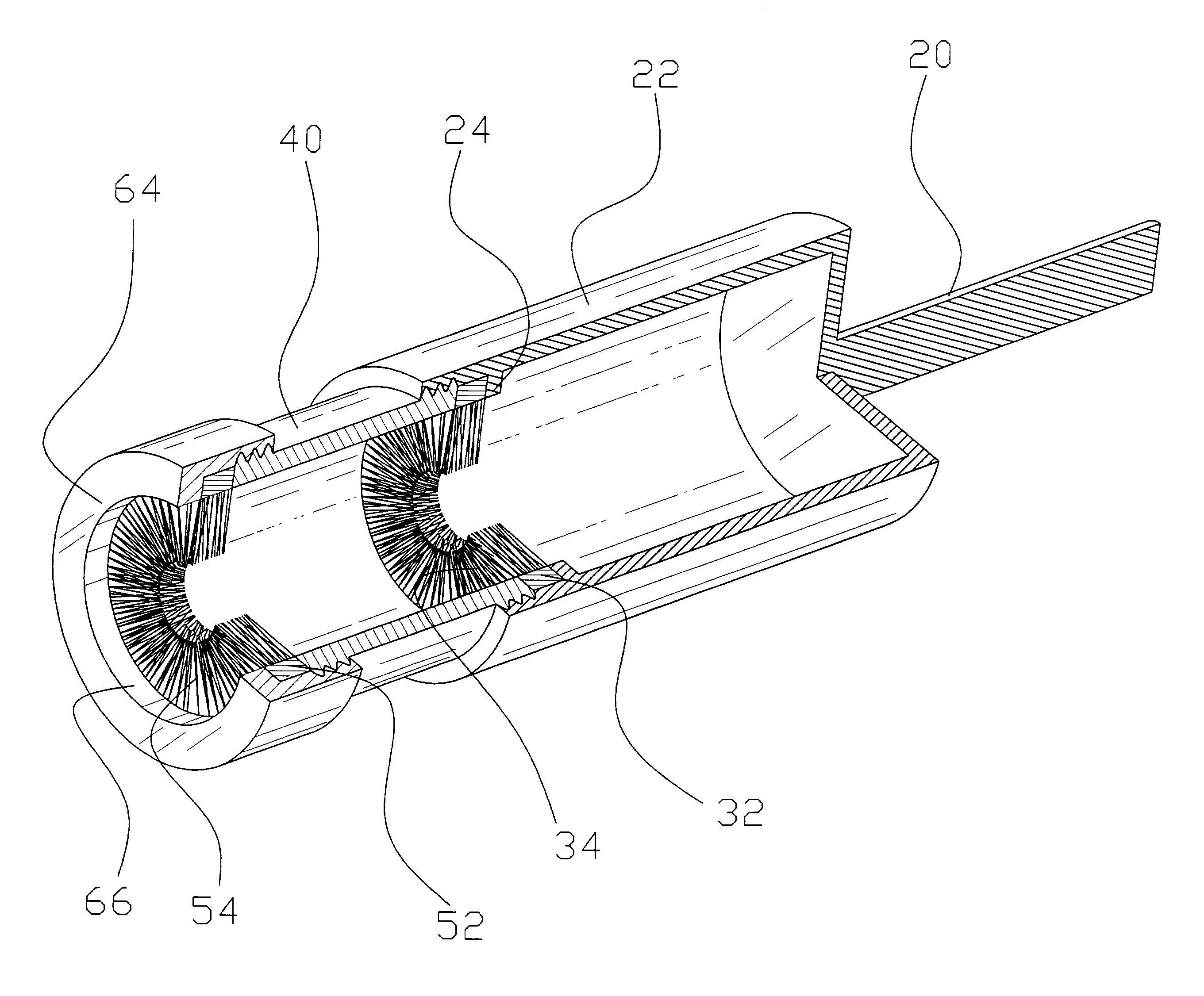
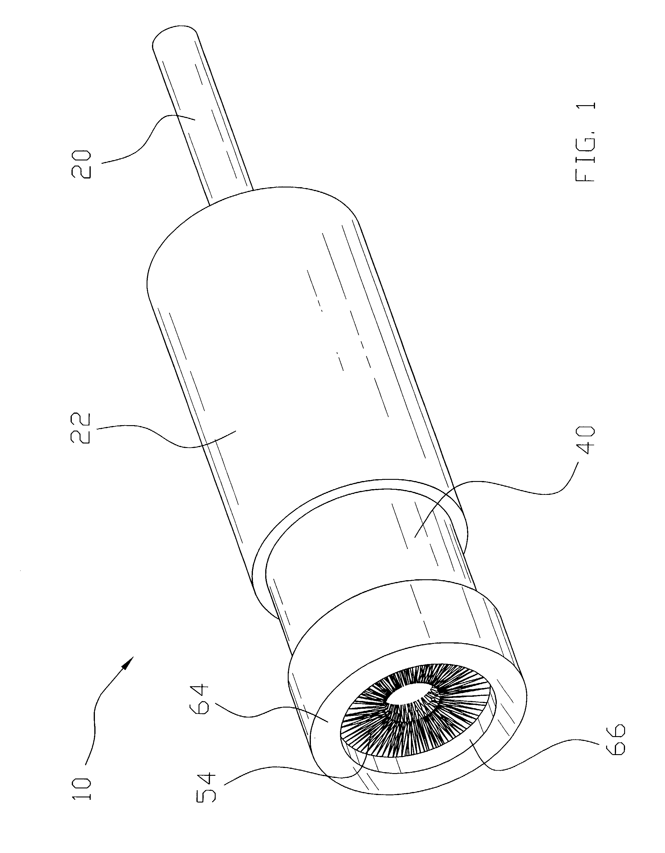
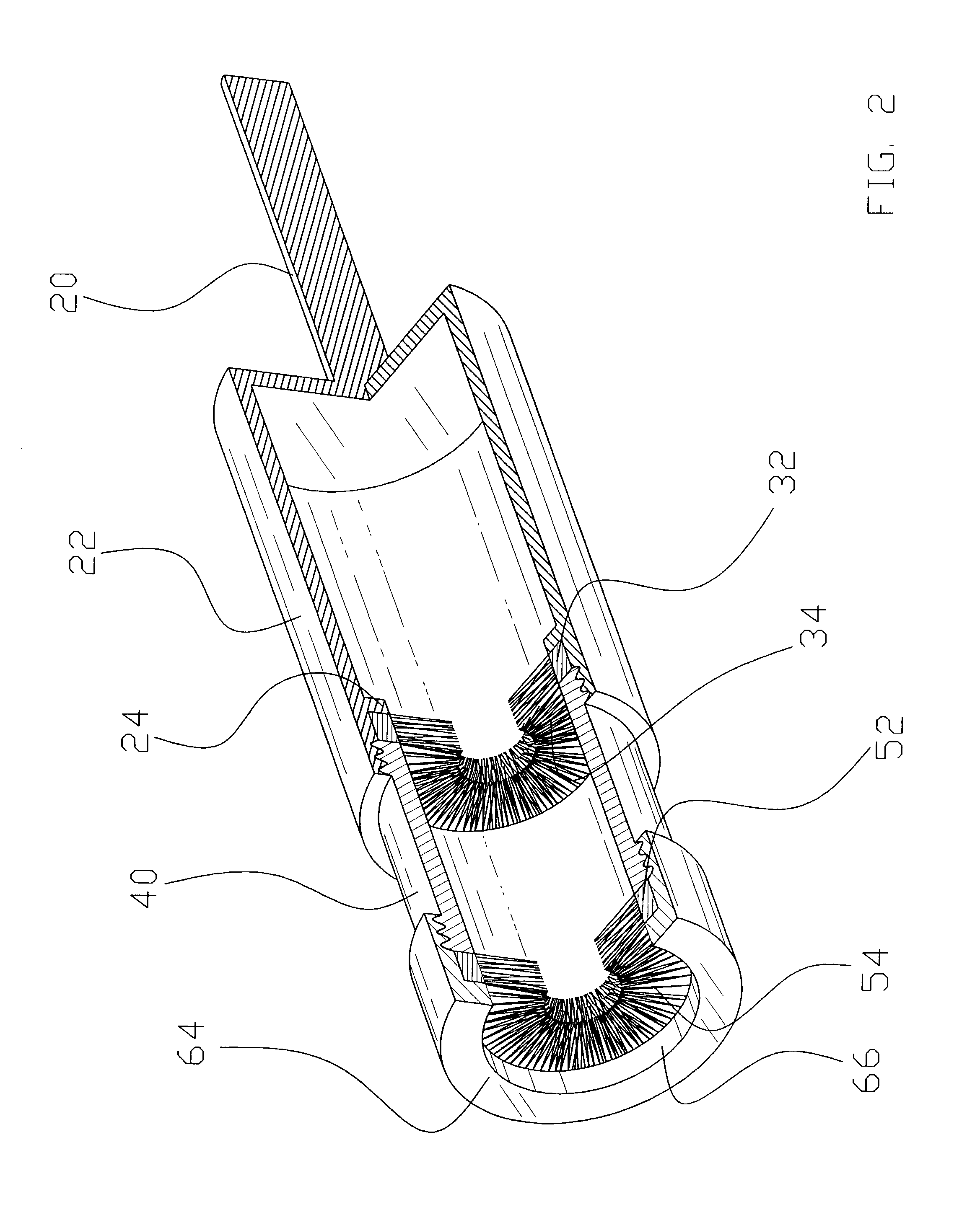
[0031]Turning now descriptively to the drawings, in which similar reference characters denote similar elements throughout the several views, FIGS. 1 through 6 illustrate a bolt cleaning system 10, which comprises a shaft member 20, an inner member 22 attached to the shaft member 20 having an annular member 24, a first cleaning unit 30 removably positionable within the inner member 22, a connector member 40 connectable to the inner member 22, an outer member 60 connectable to the connector member 40, and a second cleaning unit 50 removably positioned between the connector member 40 and the outer member 60.

[0032]As shown in FIGS. 1 through 3 of the drawings, the shaft member 20 is comprised of an elongate rigid structure. The shaft member 20 is preferably positionable and connectable within a coupler of a conventional drive unit 16 such as an air drill, electric drill or hand drill. The shaft member 20 may have various cross sectional shapes commonly utilized within the tool industry ...


PUM


Abstract

A bolt cleaning system for removing debris from the threaded portions of anchor bolts. The bolt cleaning system includes a shaft member, an inner member attached to the shaft member having an annular member, a first cleaning unit removably positionable within the inner member, a connector member connectable to the inner member, an outer member connectable to the connector member, and a second cleaning unit removably positioned between the connector member and the outer member.

Description

CROSS REFERENCE TO RELATED APPLICATIONS[0001]Not applicable to this application.STATEMENT REGARDING FEDERALLY SPONSORED RESEARCH OR DEVELOPMENT[0002]Not applicable to this application.BACKGROUND OF THE INVENTION[0003]1. Field of the Invention[0004]The present invention relates generally to anchor bolt cleaning devices and more specifically it relates to a bolt cleaning system for removing debris from the threaded portions of anchor bolts.[0005]2. Description of the Related Art[0006]Anchor bolts positioned within concrete during pouring often times become contaminated with concrete, dirt and other debris. Threaded studs welded to a structure also require cleaning of excess weld and debris accumulated upon the threaded portions thereof. Conventional methods of cleaning anchor bolts and other devices involves using a wire brush which is labor intensive and time consuming. In addition, using a wire brush often times does not completely clean the threaded portions.[0007]Examples of paten...

Claims


Application Information

Patent Timeline
Patent Type & Authority Patents(United States)
IPC IPC(8): B08B9/02A46B13/00B08B1/04B08B9/023
CPCA46B13/001B08B9/057B08B9/021B08B9/023B08B1/04A46B2200/3093B08B1/34B08B1/32
Inventor SAURER, JAMES M.
Owner SAURER JAMES M
Learn More