Methods and apparatus for assembling gas turbine engines

a gas turbine engine and assembly method technology, applied in the field of gas turbine engines, can solve the problems of complicated assembly of the struts to the engine frame, and the manufacturing and assembly costs of such frames may be more expensive and time-consuming than associated with other known frames

Active Publication Date: 2006-01-10
GENERAL ELECTRIC CO
View PDF8 Cites 71 Cited by
  • Summary
  • Abstract
  • Description
  • Claims
  • Application Information

AI Technical Summary

Problems solved by technology

However, airflow and structural design requirements of such fairings may complicate the assembly of the struts to the engine frame.
Accordingly, because of the additional assembly and coupling hardware associated with multi-piece frames, and because of the tolerances that may be necessary to meet structural requirements, manufacturing and assembly costs of such frames may be more costly and time-consuming than associated with other known frames.

Method used


Image

  • Methods and apparatus for assembling gas turbine engines
  • Methods and apparatus for assembling gas turbine engines
  • Methods and apparatus for assembling gas turbine engines

Examples


Embodiment Construction

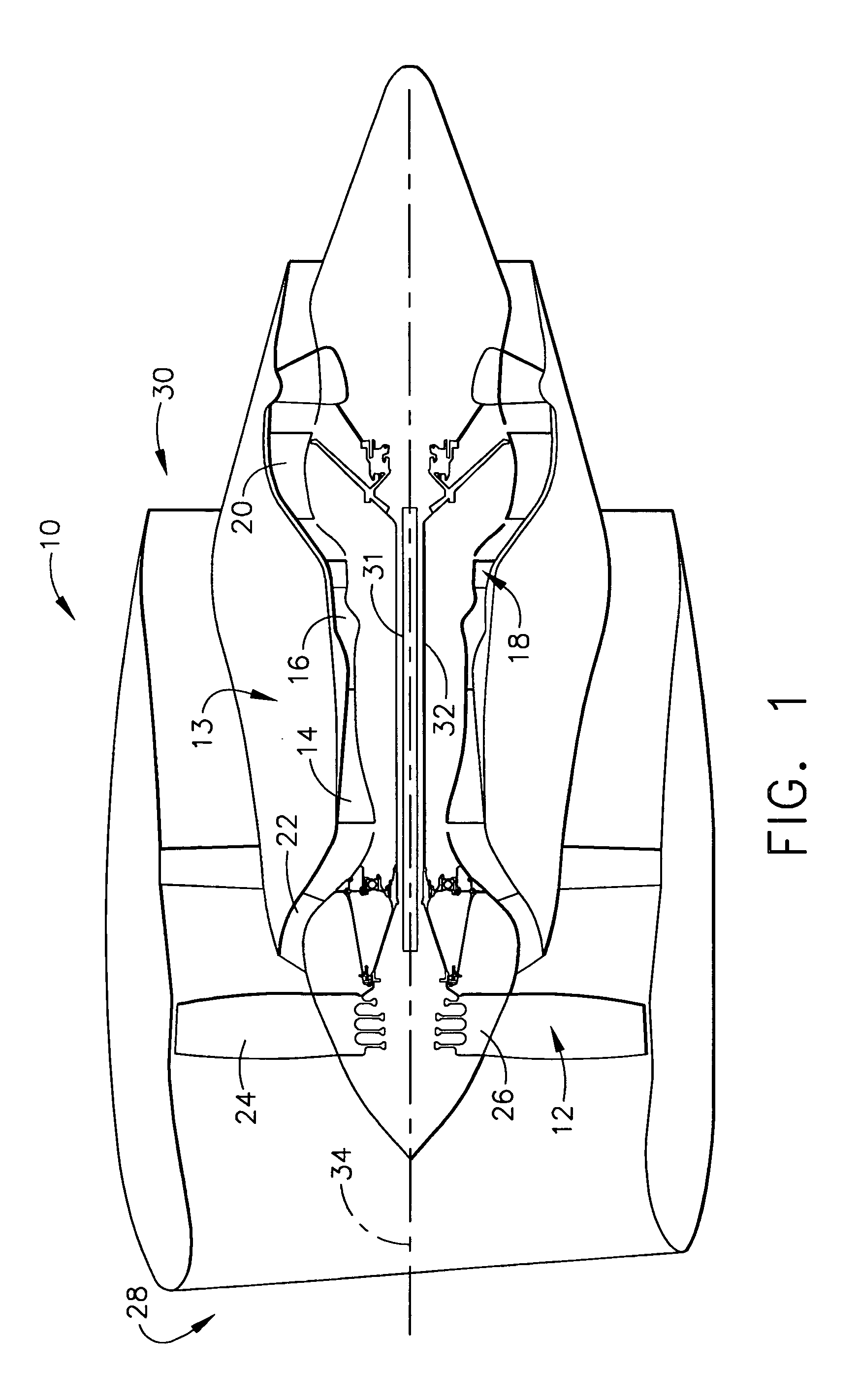
[0013]FIG. 1 is a schematic illustration of a gas turbine engine 10 including a fan assembly 12 and a core engine 13 including a high pressure compressor 14, and a combustor 16. Engine 10 also includes a high pressure turbine 18, a low pressure turbine 20, and a booster 22. Fan assembly 12 includes an array of fan blades 24 extending radially outward from a rotor disc 26. Engine 10 has an intake side 28 and an exhaust side 30. In one embodiment, the gas turbine engine is a GE90 available from General Electric Company, Cincinnati, Ohio. Fan assembly 12 and turbine 20 are coupled by a first rotor shaft 31, and compressor 14 and turbine 18 are coupled by a second rotor shaft 32.

[0014]During operation, air flows through fan assembly 12, in a direction that is substantially parallel to a central axis 34 extending through engine 10, and compressed air is supplied to high pressure compressor 14. The highly compressed air is delivered to combustor 16. Airflow (not shown in FIG. 1) from comb...


PUM

PropertyMeasurementUnit
thicknessaaaaaaaaaa
areaaaaaaaaaaa
temperatureaaaaaaaaaa

Abstract

A method facilitates assembling a gas turbine engine. The method comprises providing an engine frame including an integrally formed outer band, an inner band, and a plurality of circumferentially-spaced apart struts extending radially therebetween, and providing at least one fairing that is formed as an integral single piece casting and includes a first sidewall and a second sidewall connected at a leading edge and a trailing edge such that at least one cooling chamber is defined therebetween. The method also comprises coupling the at least one fairing around at least one strut such that the strut extends through the fairing at least one cooling chamber and such that during the coupling process the fairing is only transitioned axially around the strut rather being slid radially along the strut.

Description

STATEMENT REGARDING FEDERALLY SPONSORED RESEARCH & DEVELOPMENT[0001]The government may have rights in this invention pursuant to government contract number N00019-01-C-0147.BACKGROUND OF THE INVENTION[0002]This invention relates generally to gas turbine engines and more particularly, to methods and apparatus for assembling gas turbine engines.[0003]Known gas turbine engines include at least one rotor shaft supported by bearings which are in turn supported by annular frames. At least some known turbine frames include an annular casing that is spaced radially outwardly from an annular hub. A plurality of circumferentially-spaced apart struts extend between the annular casing and the hub. More specifically, within at least some known turbine engines, the struts, casing, and hub are integrally-formed together. In other known turbine engines, multi-piece frames are used in which only the struts and casing are integrally formed together.[0004]Because at least some of the struts extend thr...

Claims


Application Information

Patent Timeline
Patent Type & Authority Patents(United States)
IPC IPC(8): F02C7/20F01D9/02F01D9/00F01D9/04F01D9/06F01D25/16F01D25/24F02C7/00
CPCF01D9/00F01D9/065F01D25/28F01D25/162Y10T29/49346F05D2230/12
Inventor ALLEN, JR., CLIFFORD EDWARDCHARLTON, ALAN JOHN
Owner GENERAL ELECTRIC CO
Why Eureka
Try Eureka