Method of and apparatus for offshore mooring

Active Publication Date: 2006-01-10
TECH FRANCE SA
View PDF4 Cites 47 Cited by
  • Summary
  • Abstract
  • Description
  • Claims
  • Application Information

AI Technical Summary

Benefits of technology

[0003]Offshore mooring can also be accomplished using a technique known as dynamic positioning. The dynamic positioning technique involves the use of one or more propulsion devices mounted on the vessel to be moored which are operated to maintain the vessel at a specified location as determined by GPS technology. Although generally satisfactory in operation, dynamic positioning systems require the consumption of substantial amounts of fuel and are therefore expensive to operate. The fuel consumption necessary in the operation of dynamic positioning systems also raises environmental concerns.
[0004]The present invention comprises a method of and apparatus for offshore mooring which fulfills the foregoing and other requirements long since found lacking in the prior art. In accordance with a first embodiment of the apparatus of the invention, a clamping apparatus is provided at the distal end of either a preset catenary mooring line or a preset taut-leg mooring line. A wire or chain pendant extends from the vessel to be moored through the clamping apparatus. The distal end of the pendant is connected to a line which extends to a winch mounted on an anchor handling vessel. The winch is utilized to pull the pendant through the clamping apparatus until a predetermined tension is exerted on the mooring line and the pendant. The clamping apparatus is then actuated to securely clamp the pendant to the mooring line while maintaining the predetermined tension. In this matter the tension necessary to properly moor the vessel at the offshore site is achieved without requiring the use of mooring winches on the vessel being moored.
[0005]In accordance with more specific aspects of the

Problems solved by technology

Winches having sufficient capacity to be used in tensioning mooring lines of the type used in offshore mooring operations are exceedingly expensive, but are used only intermittently, such as during the initial mooring of the vessel upon which they are installed, during relocation of the vessel, and in response to cha

Method used


Image

  • Method of and apparatus for offshore mooring
  • Method of and apparatus for offshore mooring
  • Method of and apparatus for offshore mooring

Examples


first embodiment

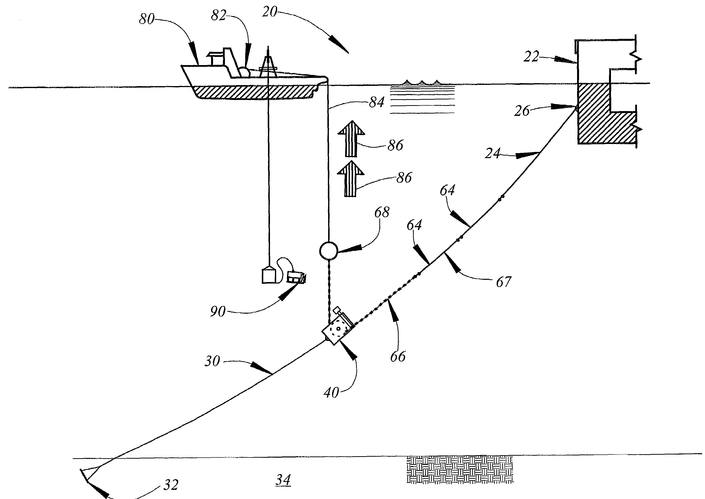
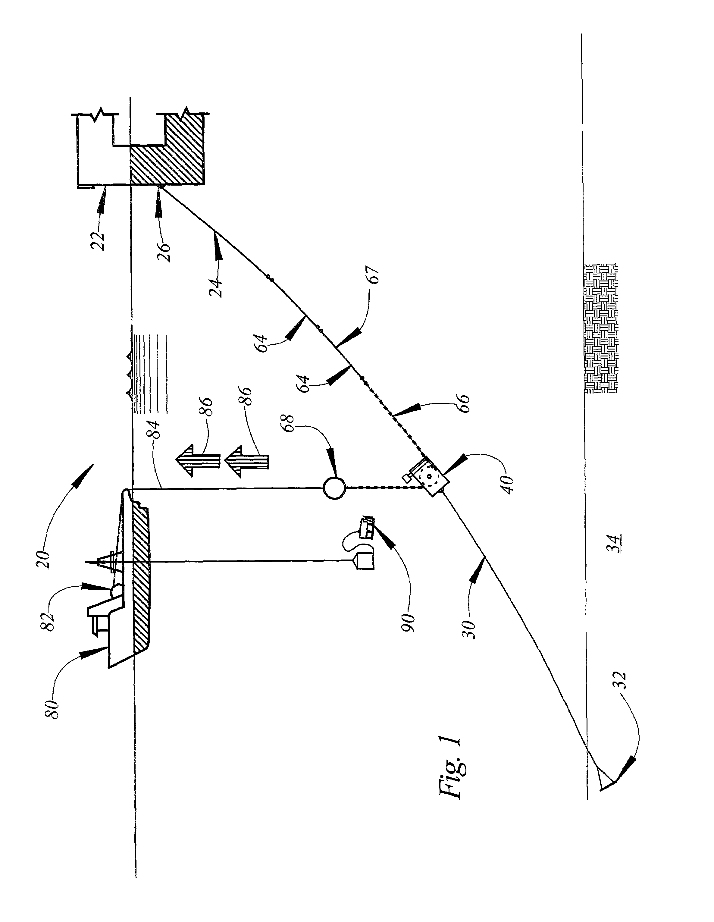
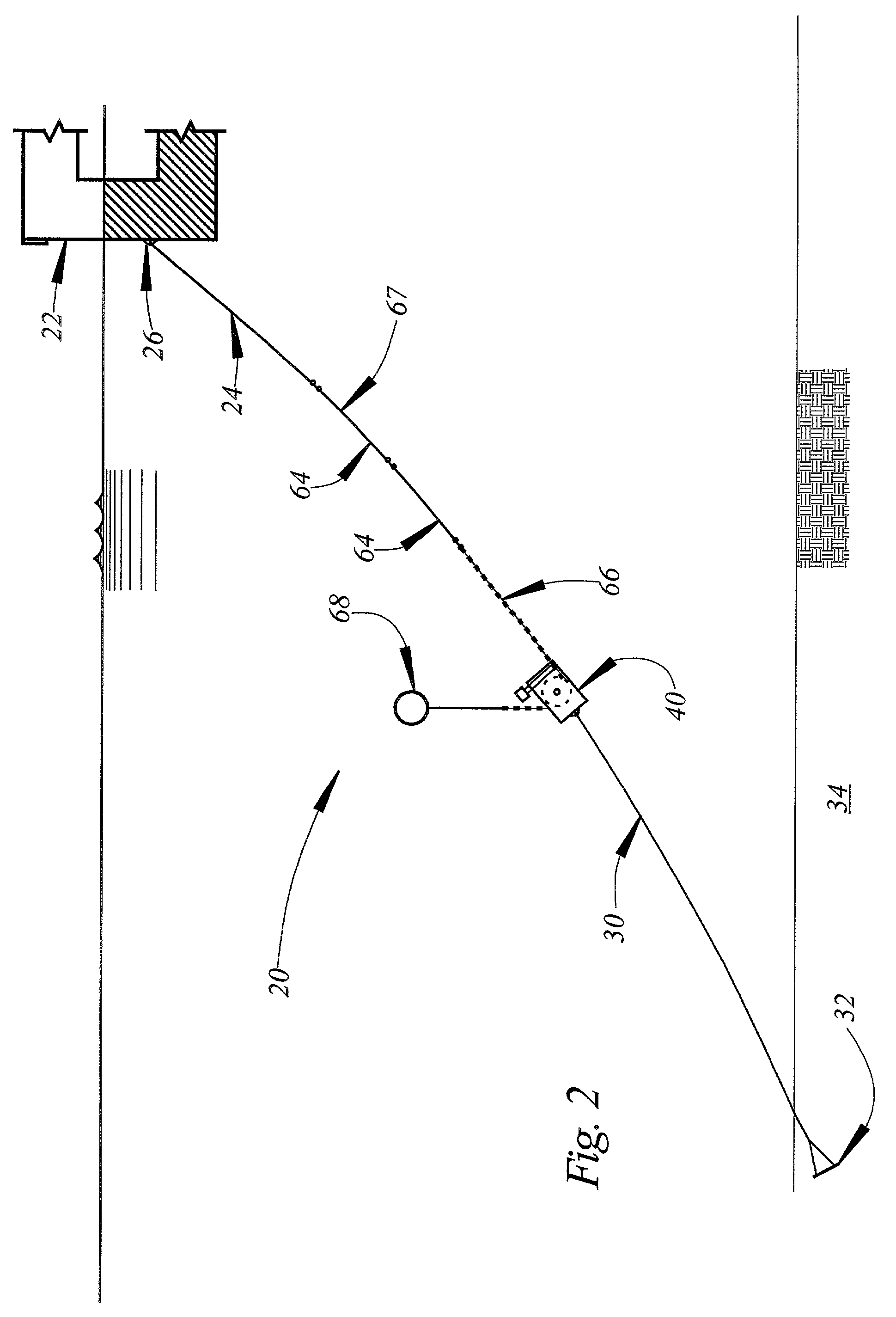
[0043]Referring now the Drawings, and particularly to FIGS. 1 through 6 thereof, there is shown method of and apparatus for offshore mooring 20 comprising the invention. In accordance with the invention, a vessel to be moored (VTBM) 22 is located at an offshore venue. The VTBM may comprise a mobile offshore drilling unit, a floating production platform (monohull or semisubmersible), a SPAR, or any other vessel requiring offshore mooring. A plurality of wire or chain mooring attachment pendants 24 are secured to the VTBM at spaced apart locations around the circumference thereof. Each mooring attachment pendant 24 is secured to the VTBM through a padeye 26. Each padeye 26 is provided with a tension measuring device such as a strain gauge. The function of the tension measuring device is to produce an output indicative of the tension applied to its associated padeye 26 by the mooring attachment pendant 24 secured thereto.

[0044]The apparatus for offshore mooring 20 further includes a pl...

third embodiment

[0072]Referring to FIGS. 17 through 20, inclusive, there is shown an apparatus for offshore mooring 190 comprising the invention. The apparatus 190 comprises a pin 192. The remaining components of the apparatus 190 are rotatably and / or pivotally supported on the pin 192. The apparatus 190 further includes a slotted pulley or sheave 194 which is rotatably supported on the pivot pin 192. The slotted pulley 194 includes an inner narrow slot 196 which receives the nominally vertically oriented links of a chain 198, and an outer wide slot 200 which receives the nominally horizontally oriented links of the chain 198.

[0073]The apparatus for offshore mooring 190 further includes an attachment arm 202 which is pivotally supported on the pin 192. A shackle 204 is mounted at one end of the attachment arm 202, and a shackle 206 is mounted at the opposite end thereof. The shackle 204 is utilized whenever it is necessary to raise or lower the apparatus for offshore mooring 190 relative to an anch...

fourth embodiment

[0078]A method of offshore mooring 250 comprises the invention as illustrated in FIGS. 21 through 31, inclusive. Referring first to FIG. 21, a vessel to be moored (VTBM) 252 is located at an offshore mooring site. Although the VTBM illustrated in FIGS. 21 through 31 is a mobile offshore drilling unit, the method of offshore mooring 250 is equally adapted to the mooring of floating production platforms, SPARs, as well as other vessels requiring offshore mooring. The VTBM 252 has a plurality of connection pendants 254 secured thereto.

[0079]A mooring line 260 includes a ground chain 262 which is secured to an anchor 264. The anchor 264 is securely engaged with the sea floor 266 and may comprise a drag embedment anchor, a vertically loaded anchor, a driven pile, a suction anchor, a suction embedded plate anchor, or any other anchor type adapted for mooring in deep waters. A submersible buoy 268 is connected to the distal end of the mooring line 260.

[0080]Referring to FIG. 22, an anchor ...


PUM


Abstract

In a method of and apparatus for offshore mooring, a clamping apparatus includes a clamping mechanism and a pulley. A mooring line connected to an anchor or a pendant line connected to a vessel to be moored extends through the clamping mechanism and around the pulley of the clamping apparatus. The distal end of the line extending through the clamping apparatus is connected to an anchor handling vessel. The anchor handling vessel is employed to apply a predetermined tension to the pendant line and the preset mooring line. A remote operated vehicle is then employed to actuate the clamping apparatus and to disengage the anchor handling vessel.

Description

BACKGROUND AND SUMMARY OF THE INVENTION[0001]Mobile offshore drilling units (MODUs), floating production platforms (FPPs), SPARS, and similar vessels are often moored at offshore venues utilizing either preset catenary mooring lines or preset taut-leg mooring lines. Mooring is accomplished by first attaching a plurality of preset mooring lines to the vessel to be moored, and thereafter applying a predetermined tension to each of the mooring lines. Heretofore the necessary tension has been applied to the mooring lines utilizing winches mounted on the vessel to be moored.[0002]Winches having sufficient capacity to be used in tensioning mooring lines of the type used in offshore mooring operations are exceedingly expensive, but are used only intermittently, such as during the initial mooring of the vessel upon which they are installed, during relocation of the vessel, and in response to changing conditions at the mooring site. Thus, a need exists for method of and apparatus for mooring...

Claims


Application Information

Patent Timeline
IPC IPC(8): B63B21/50B63B21/04B63B21/20
CPCB63B21/04B63B21/50B63B21/20B63B2021/505
Inventor DOVE, PETER G. S.TREU, JOHANNES JACOBUS
Owner TECH FRANCE SA
Why Eureka
Try Eureka