Fluid dispenser assembly

a fluid dispenser and assembly technology, applied in liquid handling, instruments, closures using stoppers, etc., can solve the problems of inconvenient use of hand-held or small-sized spray pumps and fluid dispensers, fluid discharge in a wrong direction, and is not suitable for other endeavors, so as to achieve convenient location and reliable

Inactive Publication Date: 2006-01-10
OGRIN RODNEY F DR
View PDF10 Cites 81 Cited by
  • Summary
  • Abstract
  • Description
  • Claims
  • Application Information

AI Technical Summary

Benefits of technology

[0010]The present invention is directed to a fluid dispenser that is easily located, does not require a user to depart from his or her work station in order to use the spray-pump, and can reliably be operated with a single hand without tipping over the spray pump, twisting the spray head, or otherwise discharging the sprayer contents in a wrong direction. Additionally, the invention permits one hand of a user to remain free while dispensing and receiving the discharged product. Moreover, the invention provides for the interconnection of a pump means and fluid actuating parts that are easily disengagable as a unit from a dispenser housing.
[0013]The pump body is secured to a connector means which, in turn, releasably constrains the receptacle within the outer housing. The connector means also provides retention constraints for the movable cover. In this way, a fluid actuating unit is created comprising the cover, pump assembly and connector means which can be moved as a unit from the housing to provide ready access to the removable receptacle. This allows the receptacle to be refilled and replaced, or be discarded.

Problems solved by technology

However, a variety of inconveniences attend the use of hand-held or small sized spray pumps and fluid dispensers.
Similarly, such force can rotate a spray head resulting in a fluid discharge in a wrong direction.
While the above can be suitable for some endeavors, it is ill suited for other endeavors.
Some occupations, however, involve work in an environment wherein a subject's hands become slippery or dirty while working.
But, it is time-consuming, burdensome and counterproductive to require the physician to hold a germicide sprayer with one unclean hand and squirt or spray germicide into the other.
Moreover, physicians oftentimes need to move about from room to room in a hospital or clinic where traditional hand-pump dispensers may not be conveniently located.
However, the patented dispensers of the aforementioned patents do not set forth an interconnected pump, pump cover and integration structure that simplifies the exchange of fluid receptacles.

Method used


Image

  • Fluid dispenser assembly
  • Fluid dispenser assembly
  • Fluid dispenser assembly

Examples


Embodiment Construction

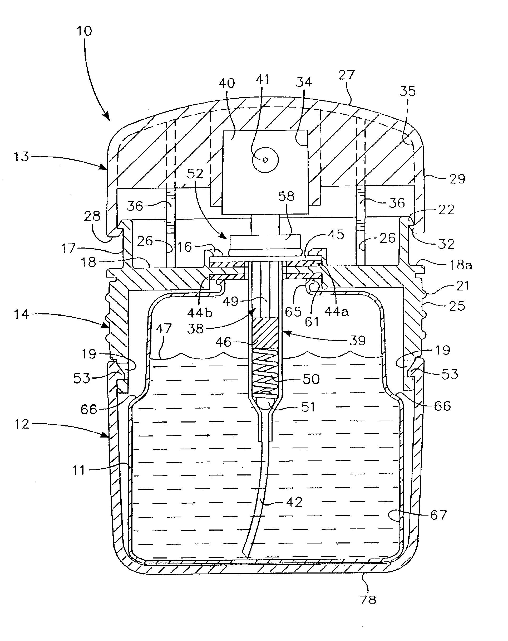
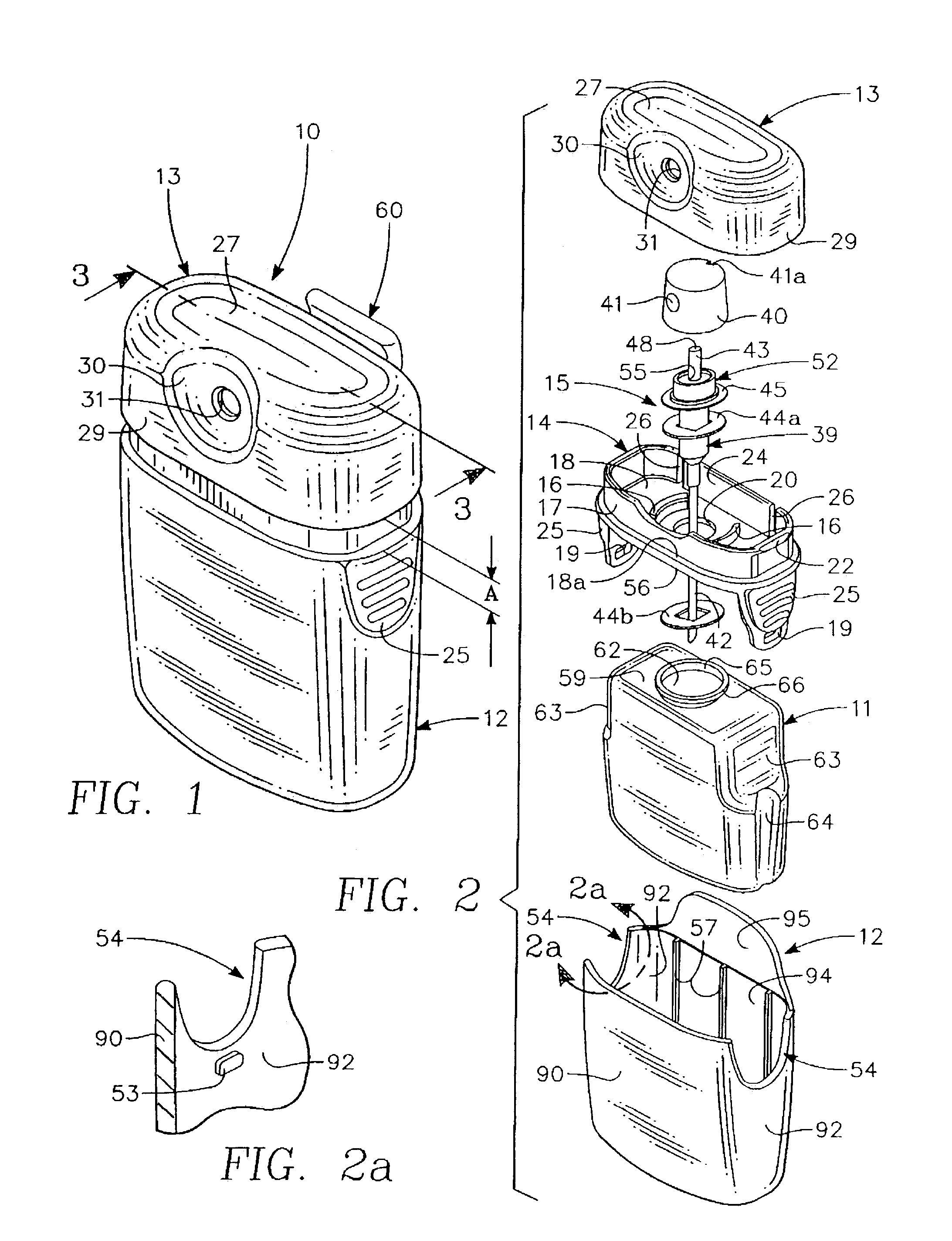
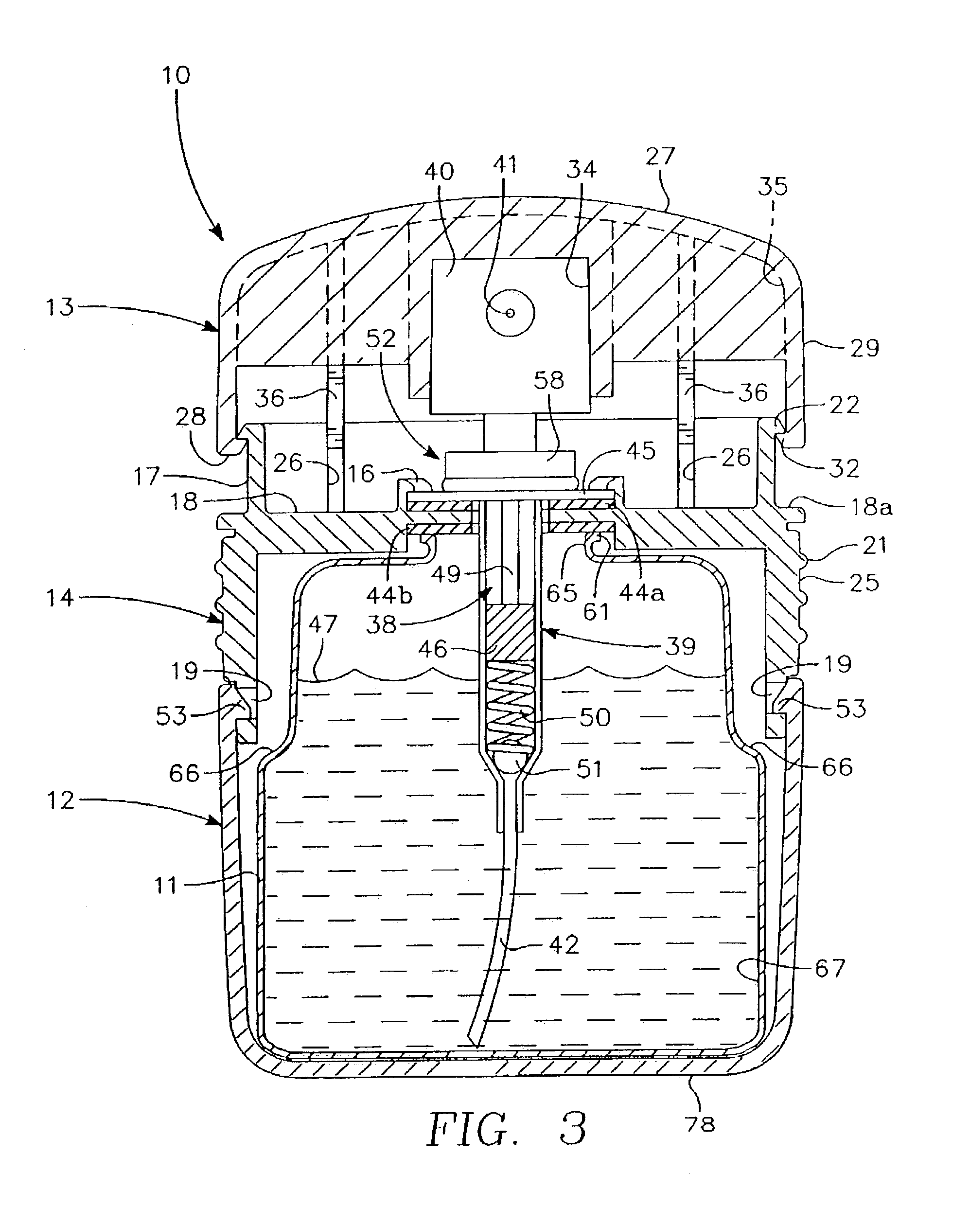
[0027]With attention to FIGS. 1, 3 and 7, the fluid dispenser of the present invention is shown generally by reference 10. The dispenser is configured to discharge a fluid 47 into the palm 86 of the actuating hand (H) of a user. The overall dispenser has a generally polygonal shape with a dome-shaped upper cover 13. The cover has a top surface 27 and an open interior 35. From the top surface 27 is a downwardly extending peripheral skirt 29. A front portion of the skirt is provided with a concave indentation 30 that includes a side opening 31. The skirt 29 terminates at bottom edge 28.

[0028]Extending inwardly from the bottom edge 28 of opposing sides of the skirt 29, are lip flanges 32. The lip flanges 32 are configured to engage corresponding shoulder flanges 22 of a retainer 14, in a manner to be hereinafter described.

[0029]Extending downwardly from the top underside of cover 13 is a nozzle enclosure shown as connector part 33. The connector part 33 includes frictional engagement m...


PUM


Abstract

A fluid dispenser 10 with a replaceable receptacle 11 containing fluid 47 positioned within a housing 12. An inlet tube 42 and an outlet tube 43 are connected to a pump assembly 15 for drawing fluid from the receptacle and moving the fluid through a nozzle 80 having fluid discharge aperture 41. The nozzle is secured to a hand actuatable cover 13 which is depressable to operate the pump. The pump is mounted upon a retainer 14 which is connectable to the housing. When the receptacle becomes empty, the retainer may be disengaged from the housing, and the retainer and pump are then lifted away as one unit from the housing. The empty receptacle may then be replaced with a full one, and in reverse order, the dispenser may be reassembled.

Description

BACKGROUND OF THE INVENTION[0001]1. Field of the Invention[0002]The present invention relates generally to manual spray-pump fluid dispensers. More particularly, the present invention relates to a pump-type fluid dispenser that provides for easy replacement of fluid supply receptacles which also have the capability of being operable with the same hand that receives the dispensed fluid.[0003]2. Description of the Related Art[0004]Pump type dispensers for dispensing a fluid have become a common staple of every day life. However, a variety of inconveniences attend the use of hand-held or small sized spray pumps and fluid dispensers. Some fluid dispensers are operated from a table top, and others are held in a hand during use. The preference for usage is usually an ergonomic one, and depends largely on the shape of the fluid container and the shape and location of the spray actuator. Creams and gels, such as hand cream, are often in a container with a pump actuator that includes a horiz...

Claims


Application Information

Patent Timeline
Patent Type & Authority Patents(United States)
IPC IPC(8): B67D5/60B05B11/00B67D7/78B65D88/54G01F11/06G01F11/30G01F11/36G01F11/42
CPCB05B11/0005B05B11/0054B05B11/0043B05B11/0037B05B11/0038B05B11/026
Inventor CAGLE, RONALD C.
Owner OGRIN RODNEY F DR
Why Eureka
Try Eureka