Electrical connector housing having a bridging piece between circuit boards connected to a receiving unit

a technology of electrical connectors and bridging pieces, which is applied in the direction of electrical apparatus casings/cabinets/drawers, fixed connections, coupling device connections, etc., can solve the problems of increasing the number of parts required in the above configuration, increasing the conductor pattern, and increasing the number of layers of printed circuit boards. , to achieve the effect of simplifying the connecting operation, reducing the number of parts, and facilitating the arrangement of printed circuit board patterns

Inactive Publication Date: 2006-01-10
SUMITOMO WIRING SYST LTD
View PDF23 Cites 25 Cited by
  • Summary
  • Abstract
  • Description
  • Claims
  • Application Information

AI Technical Summary

Benefits of technology

[0009]Accordingly, an object of various aspects of the present invention is to provide an electrical connector housing containing a plurality of printed circuit boards, in which connection structures between a printed circuit board and an outside connector, as well as between respective printed circuit boards, are improved, so that the number of parts can be reduced, the connecting operation can be simplified and the patterns of printed circuit boards can be arranged more freely. As a result, excessive increase in the number of printed circuit boards can be avoided, and the size and weight of the electrical connector housing can be reduced.
[0032]Further, when a joint terminal is provided in the connector, the conductors of the first and second printed circuit boards can be connected to each other through that connector. Such a configuration confers more operational freedom on the conductor patterns of the printed circuit boards and reduces unnecessary space. Further, it can reduce the number of layers of the printed circuit boards, and reduce the size and manufacturing costs of the electrical connector housing.
[0033]Further, the terminal piece that connects the conductor of the first printed circuit board to that of the second printed circuit board can be formed into a U-shape, so that it can be soldered from the same side, and operation is simplified.
[0034]In the above structure, a press-fit unit may be placed into contact, through its press-fit terminal, with a terminal hole which may include a conductor in its internal face. Thus, when the first and second printed circuit boards are connected by this press-fit terminal, the soldering operation between the conductor and the terminal can be obviated. The press-fit terminal enables to connect two separate sites by a single insertion operation, and increases work efficiency greatly.
[0035]Further, when several printed circuit boards are superposed, more connecting points are required for conductors on the printed circuit boards. This creates constraints for setting conductor patterns and increases non-usable areas. However, when the conductors on the first and second printed circuit boards are connected directly by the above terminal piece, there is more freedom for setting conductor patterns, and a high-density wiring becomes possible.

Problems solved by technology

However, the above configuration requires an increased number of parts, as the number of connectors and of connecting sites between the conductors of printed circuit boards increases.
Moreover, such a configuration creates many constraints and unnecessarily increases conductor patterns.
As a result, the number of layers of the printed circuit boards must be increased, which in turn raises material costs and increases the size and weight of the electrical connector housing manufactured.
Also, dies for forming busbars are very expensive.
This tendency has created new problems, namely how to simplify the connections between a printed circuit board and an outside connector, as well as between respective printed circuit boards.

Method used


Image

  • Electrical connector housing having a bridging piece between circuit boards connected to a receiving unit
  • Electrical connector housing having a bridging piece between circuit boards connected to a receiving unit
  • Electrical connector housing having a bridging piece between circuit boards connected to a receiving unit

Examples


Embodiment Construction

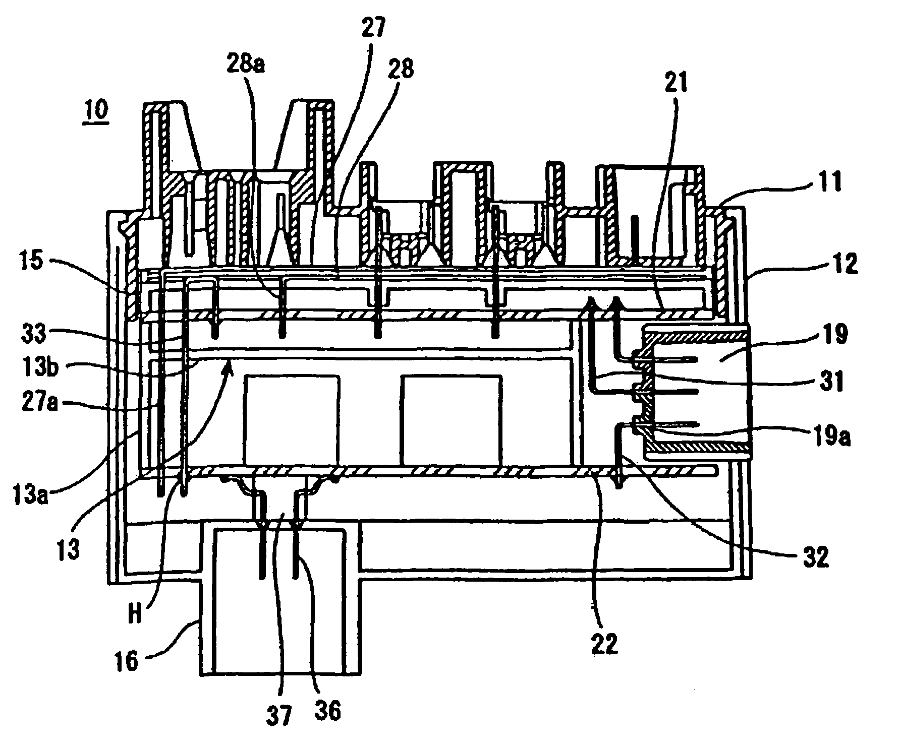
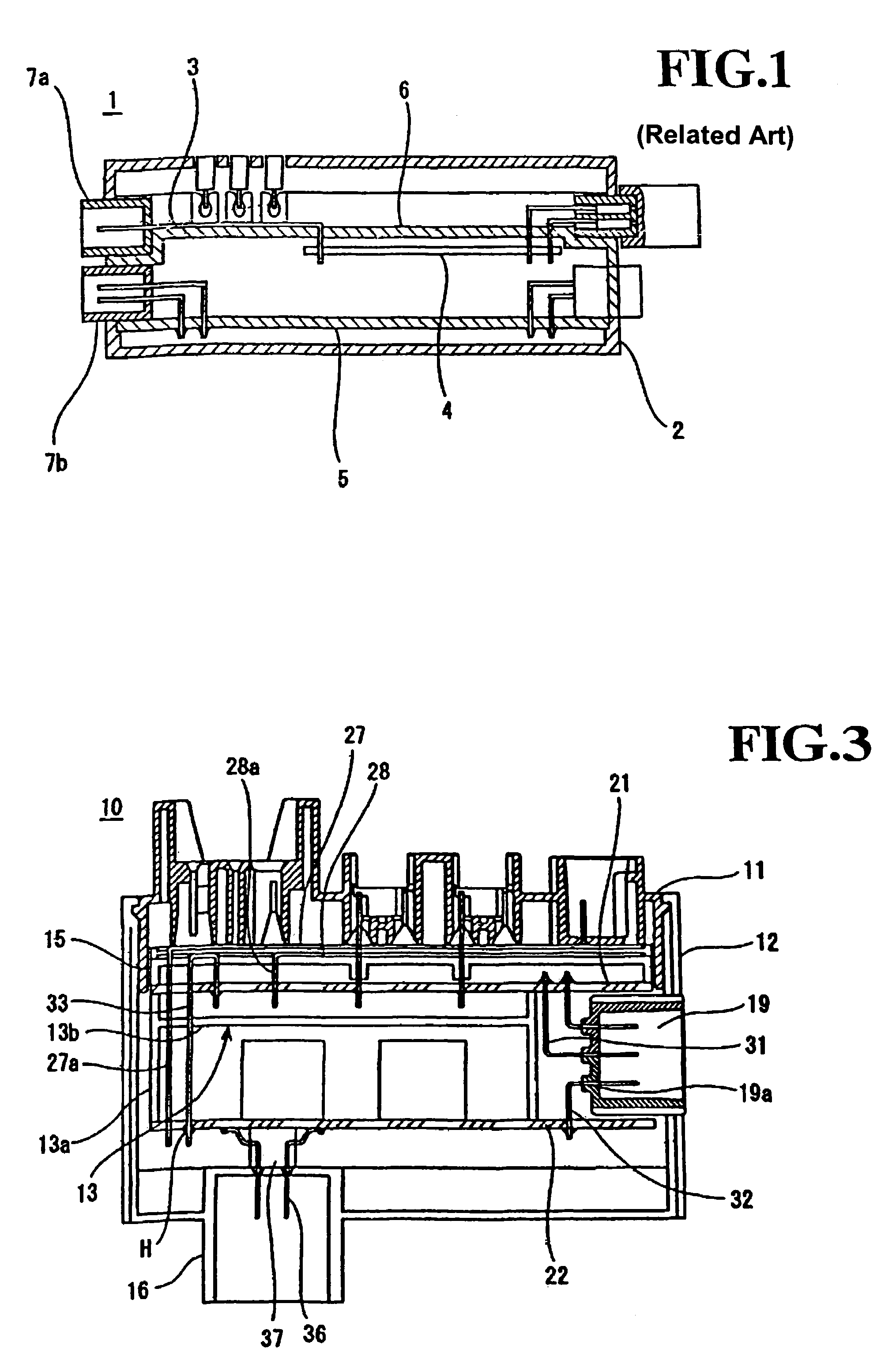
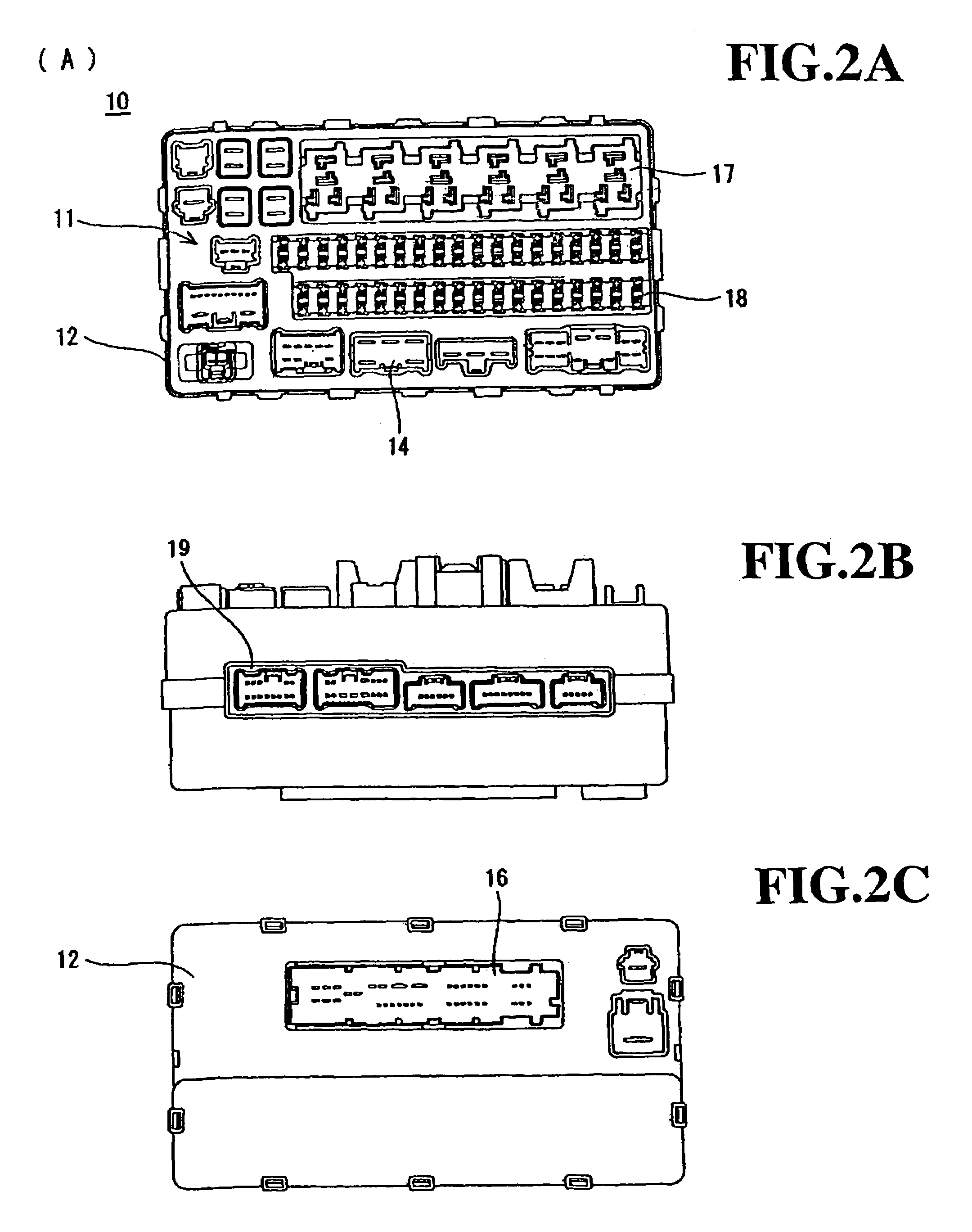
[0054]FIGS. 2 to 5 show an electrical connector housing 10 according to a first embodiment of the invention. This housing 10 is used to connect a wire harness for vehicles. It includes a first (e.g., upper) casing 11 and a second (e.g., lower) casing 12, and contains a first printed circuit board 21, a second printed circuit board 22 and busbars 27 and 28.

[0055]As shown in FIG. 3, the casings 11 and 12 contain a-board holder 13 that is formed of e.g., two flanges 13a, each with first and second ends (corresponding respectively to the upper and lower ends in FIG. 3), and e.g., a web plate 13b which bridges the two flanges 13a substantially halfway between the first and second ends. The first printed circuit board 21 is fixed on the first end of the flanges 13a, and the second printed circuit board 22 is fixed on the second end of the flanges 13a. A busbar-layer support casing 15 is provided above the first printed circuit board 21.

[0056]First and second busbars 27 and 28 are placed o...


PUM


Abstract

The invention relates to an electrical connector housing having a first casing, a second casing and a sidewall, and including a first printed circuit board and a second printed circuit board superposed with a given space. The first printed circuit board includes at least a first conductor and the second printed circuit board includes at least a second conductor. The electrical connector housing further includes a connector-receiving portion projecting from the sidewall and placed at a position between the first and second printed circuit boards. The first conductor on the first printed circuit board is connected to a first terminal device, while the second conductor on the second printed circuit board is connected to a second terminal device, and the first and second terminal devices protrude at the connector-receiving portion, so that they are adapted to connect to a terminal of an outside connector to be inserted into the connector-receiving portion.

Description

CLAIM FOR PRIORITY[0001]The present disclosure relates to subject-matter contained in and claims priority to Japanese Application No. 2003-170036, filed on Jun. 13, 2003.BACKGROUND OF THE INVENTION[0002]1. Field of Invention[0003]The present invention relates to an electrical connector housing for installation aboard vehicles, and in particular to a housing whose internal circuit conductors are composed of a plurality of printed circuit boards. In the present invention, the electrical connector housing is designed such that connections with outside circuits can be made very easily.[0004]2. Description of Related Art[0005]As shown in FIG. 1, a common electrical connector housing has a casing 2, in which a plurality of circuit elements (such as busbars 3 for internal circuits, electrical cables 4, printed circuit boards 5, etc.) are superposed on an insulating plate 6. An example of such a connector is described in more detail in document JP-A-2000-92659. The external face of the casi...

Claims


Application Information

Patent Timeline
Patent Type & Authority Patents(United States)
IPC IPC(8): H01R12/00H05K1/00H02G3/16H01R13/516H05K1/14H05K3/34H05K3/36H05K5/00
CPCH05K1/144H05K7/026H01R12/52H05K1/145H05K3/3447H05K3/368Y10S439/949H05K2201/10189H05K2201/10363H01R12/523H05K2201/09063
Inventor NAITOU, TSUTOMUOKA, TATSUYA
Owner SUMITOMO WIRING SYST LTD
Why Eureka
Try Eureka