Rotary electric machine stator

a technology of electric machines and stators, which is applied in the direction of windings, dynamo-electric components, and magnetic circuit shapes/forms/construction, etc., can solve the problems that the distance between the magnetic teeth b>31/b> cannot be reduced further, and achieve the effect of improving the space factor of the stator, reducing the gap between the magnetic teeth, and increasing the number of turns

Inactive Publication Date: 2006-01-10
HONDA MOTOR CO LTD
View PDF17 Cites 51 Cited by
  • Summary
  • Abstract
  • Description
  • Claims
  • Application Information

AI Technical Summary

Benefits of technology

[0011]A stator for use in a rotating electrical machine is constituted by arranging the prescribed number of stator units in the circumferential direction of a stator core having a circular ring shape. The stator units provide magnetic teeth that project inwardly in the radial direction of the stator core. Coils are wound about the magnetic teeth via insulating members. Each of the insulating members has thick portions that slightly project opposite to each other in the circumferential direction of the magnetic tooth, so that one thick portion formed on one insulating member is shifted in position compared with the other thick portion formed on the other adjoining insulating member. Thus, it is possible to improve the space factor in the stator, wherein the coils can be increased in numbers of turns, or the gaps between the magnetic teeth can be reduced without reducing the numbers of turns of the coils. This guarantees noticeable improvement of the torque or electric power generation, or this may realize downsizing of the machine without causing unwanted reduction of power.

Problems solved by technology

In addition, there is a problem in that intervals of distance between the magnetic teeth 31 cannot be reduced further.

Method used


Image

  • Rotary electric machine stator
  • Rotary electric machine stator
  • Rotary electric machine stator

Examples


Embodiment Construction

[0021]This invention will be described in further detail by way of examples with reference to the accompanying drawings.

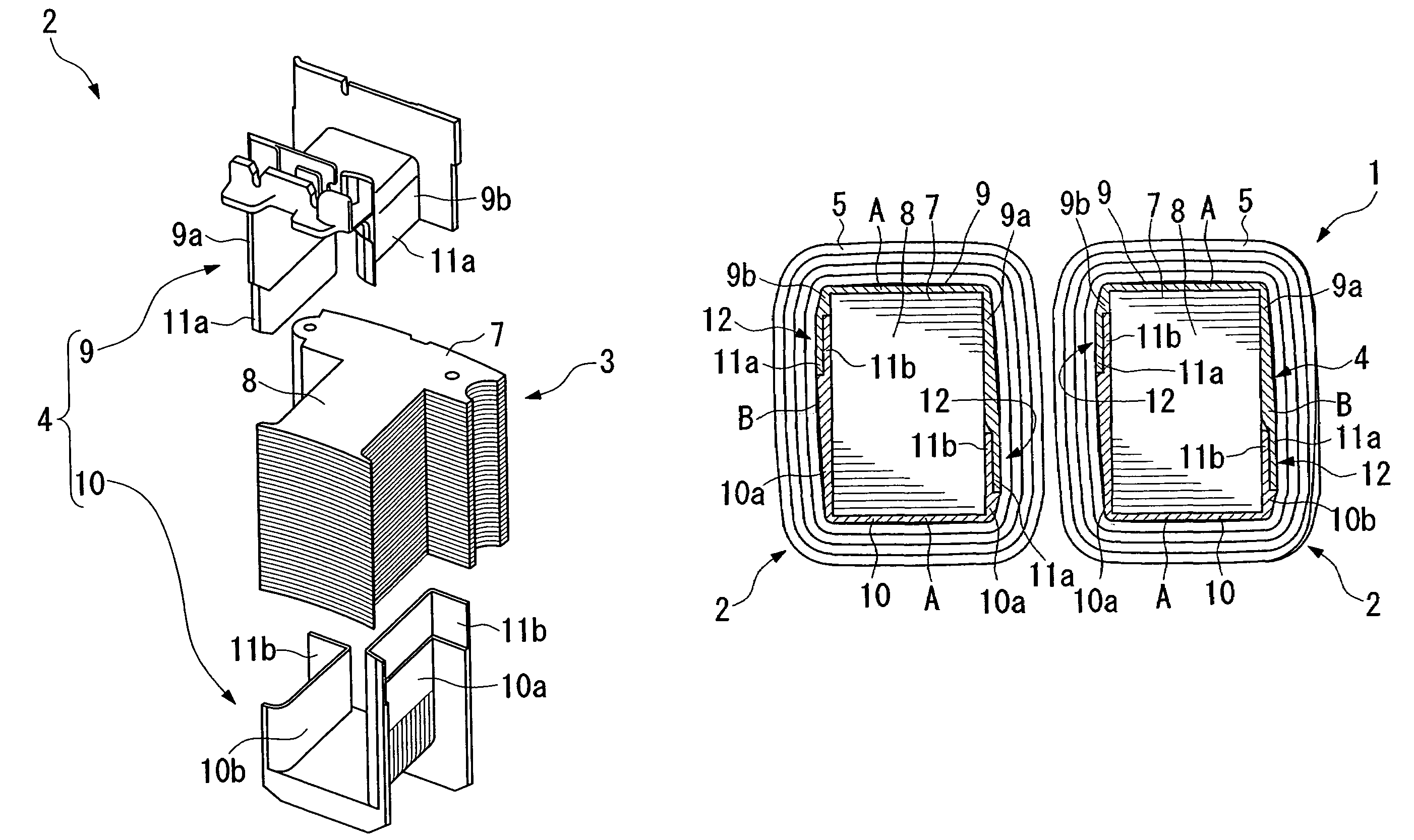
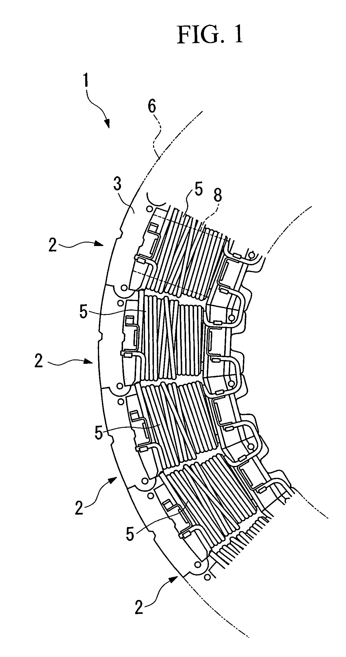
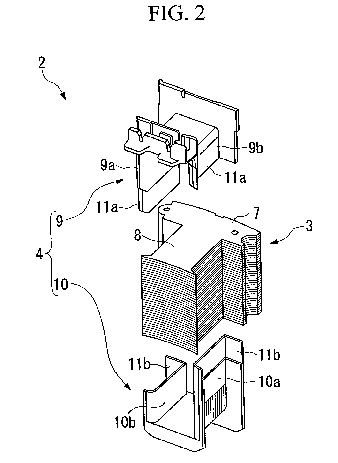
[0022]FIG. 1 shows selected parts of a stator 1 in accordance with the first embodiment of the invention, wherein as similar to the conventional stator 30 shown in FIG. 5, the stator 1 of the first embodiment has a circular ring shape and is constituted by arranging the prescribed number of stator units 2 in the circumferential direction thereof. FIG. 2 shows an exploded perspective view showing an assembly of each stator unit 2, which comprises a core unit 3, an insulating member 4, and a coil 5. The prescribed number of core units 3 are arranged in the circumferential direction to form a stator core 6 having a circular ring shape.

[0023]The stator unit 2 of the present embodiment is constituted similar to the foregoing stator unit 32 shown in FIG. 6. That is, the core unit 3 corresponds to a lamination or stacking of plural magnetic steel sheets 7, which provides ...


PUM


Abstract

A stator for use in a rotating electrical machine is constituted by arranging the prescribed number of stator units in the circumferential direction of a stator core having a circular ring shape. The stator units provide magnetic teeth that project inwardly in the radial direction of the stator core. Coils are wound about the magnetic teeth via insulating members. Each of the insulating members arranges thick portions that slightly project opposite to each other in the width direction of the magnetic tooth, wherein the thick portions are shifted in positions in the thickness direction of the stator core with respect to opposite sides of the magnetic teeth arranged opposite to each other. Thus, it is possible to noticeably improve the space factor in the stator.

Description

TECHNICAL FIELD[0001]This invention relates to stators for use in rotating electrical machines such as motors and generators.BACKGROUND ART[0002]A typical example of a stator for use in a rotating electrical machine such as a motor and a generator is disclosed in Japanese Unexamined Patent Publication No. 2001-25187, wherein the stator comprises a stator core having a circular ring shape, coils wound about magnetic teeth, and insulating members. Herein, the stator core corresponds to a lamination or stacking of magnetic steel sheets, from which a prescribed number of magnetic teeth project inwardly in the radial direction of the stator. The coils are wound about the magnetic teeth that are arranged in the circumferential direction of the stator, and the insulating members, each having a cylinder-like shape, are arranged to cover the magnetic teeth and are also arranged being sandwiched between the magnetic teeth and coils.[0003]FIG. 5 shows a partial structure of a stator 30 in whic...

Claims


Application Information

Patent Timeline
Patent Type & Authority Patents(United States)
IPC IPC(8): H02K3/34H02K1/18H02K3/32H02K3/46H02K3/52
CPCH02K3/325H02K3/522H02K2203/06
Inventor HORIE, TATSUROFUKUDA, KENJIKOBAYASHI, MANABU
Owner HONDA MOTOR CO LTD
Why Eureka
Try Eureka