Distance correcting apparatus of surroundings monitoring system and vanishing point correcting apparatus thereof

a technology of distance correction and surroundings monitoring system, which is applied in the direction of distance measurement, image enhancement, instruments, etc., can solve the problems of prior art that is not suitable for real time processing, the distance calculated based on parallax differs from the real one, and the stereoscopic camera has some amount of positional errors, etc., to achieve the effect of raising the accuracy of measuring distan

Inactive Publication Date: 2006-01-10
SUBARU CORP
View PDF6 Cites 52 Cited by
  • Summary
  • Abstract
  • Description
  • Claims
  • Application Information

AI Technical Summary

Benefits of technology

[0007]It is an object of the present invention to provided a surroundings monitoring apparatus capable of correcting a parallax including errors, in particular, an error caused by horizontal deviation, in parallel with a surroundings monitoring control. It is further object of the present invention to provide a surroundings monitoring apparatus in which the accuracy of mea

Problems solved by technology

In actual world, however, the stereoscopic camera has some amount of positional errors such as horizontal or vertical deviations (parallel deviations), a rotational deviation and the like, caused when the camera is installed on a vehicle and the like.
Particularly, the horizontal deviation directly produces an error in an parallax and

Method used


Image

  • Distance correcting apparatus of surroundings monitoring system and vanishing point correcting apparatus thereof
  • Distance correcting apparatus of surroundings monitoring system and vanishing point correcting apparatus thereof
  • Distance correcting apparatus of surroundings monitoring system and vanishing point correcting apparatus thereof

Examples


second embodiment

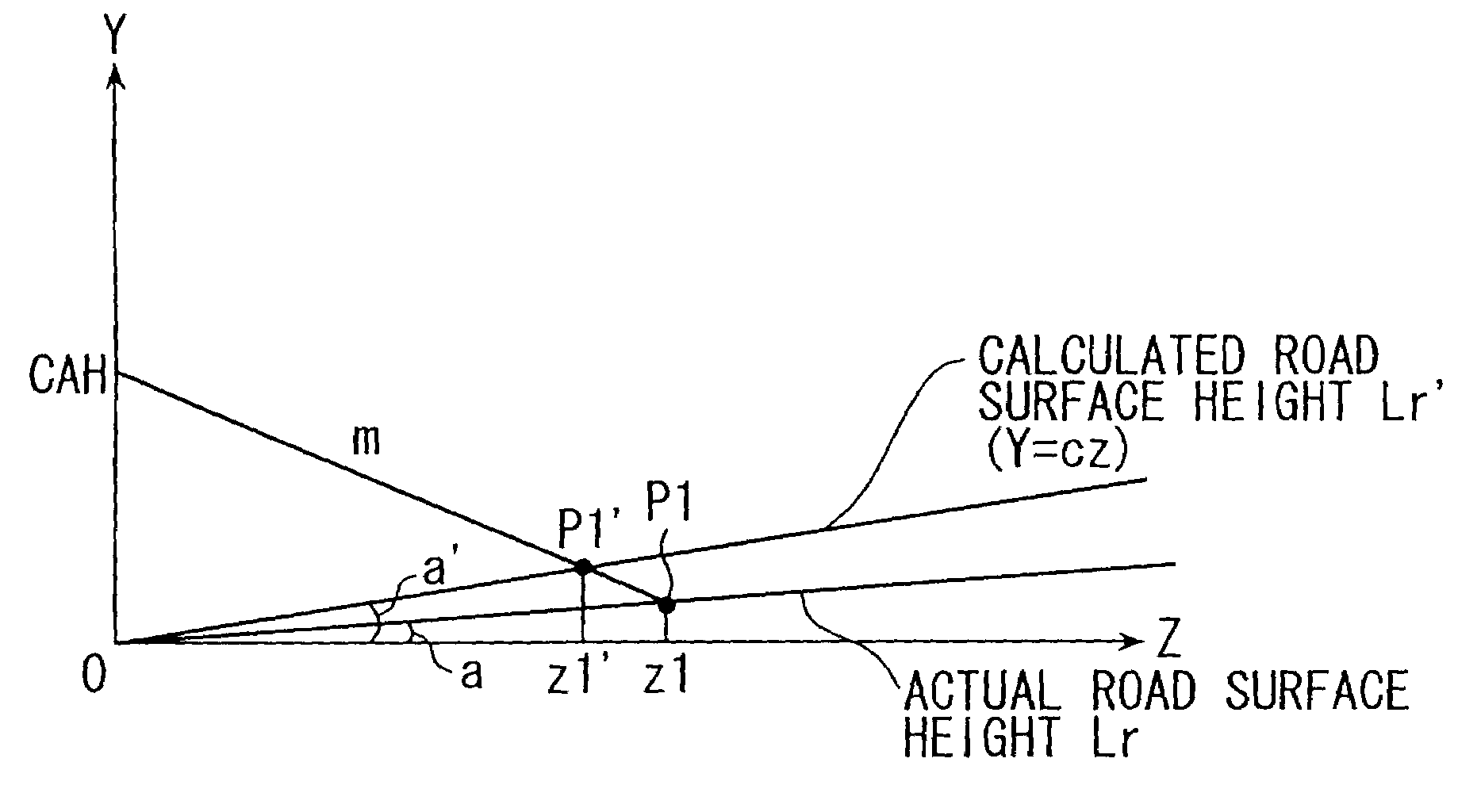
[0080]According to the second embodiment, the parallax correction value DP is updated based on the comparison relationship between the gradient a of the actual road surface height Lr (that is, gradient a of the vanishing line Lv) and the gradient a′ (that is, the parameter C identified from the lane marker models L, R) of the calculated road surface height Lr′. The steps of up-dating are the same as those shown in the flowcharts of FIGS. 2 and 3. A portion different from the first embodiment is the step 11 of FIG. 3, that is, a part where the distance calculation parameter is updated.

[0081]FIG. 5 is a flowchart showing up-dating steps of the parallax correction value DP according to the second embodiment. First, at a step 31, it is judged whether or not the product of subtracting the gradient a of the actual road surface height Lr from the gradient a′ of the calculated road surface height Lr′, is larger than a positive threshold value TH. In case where the positive judgment (YES) is...

third embodiment

[0086]The feature of this embodiment is that an affine parameter SHFT1 (shift in horizontal direction) in the affine transformation is updated according to the difference between the gradient a′ of the calculated road surface height Lr′ and the gradient a of the actual road surface height Lr.

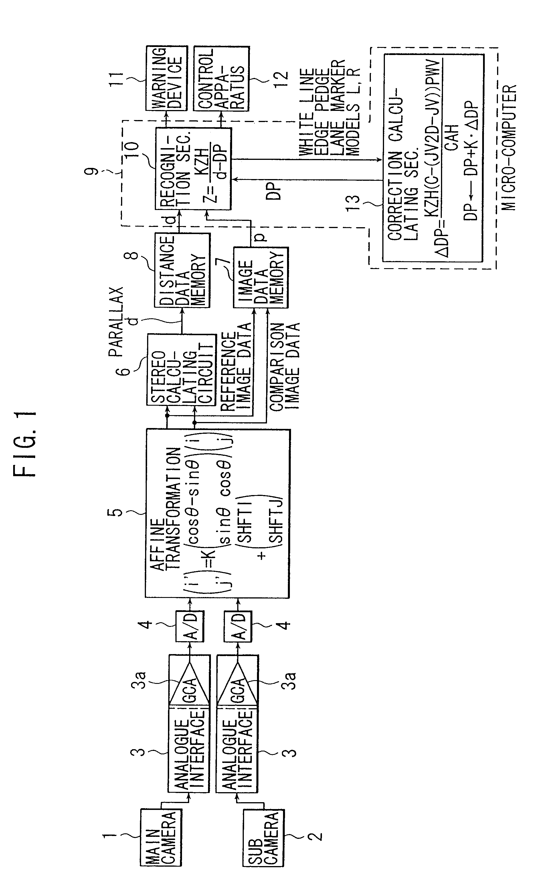
[0087]FIG. 6 is a block diagram showing the construction of a stereoscopic type vehicle surroundings monitoring apparatus according to the third embodiment. The block diagram is the same as that of FIG. 1 except for that the affine parameter SHFT1 calculated in the correction calculating section 13 is fed back to the correction circuit 5. Therefore, the components of the block diagram which are identical in both embodiments are denoted by identical reference numbers and are not described in detail.

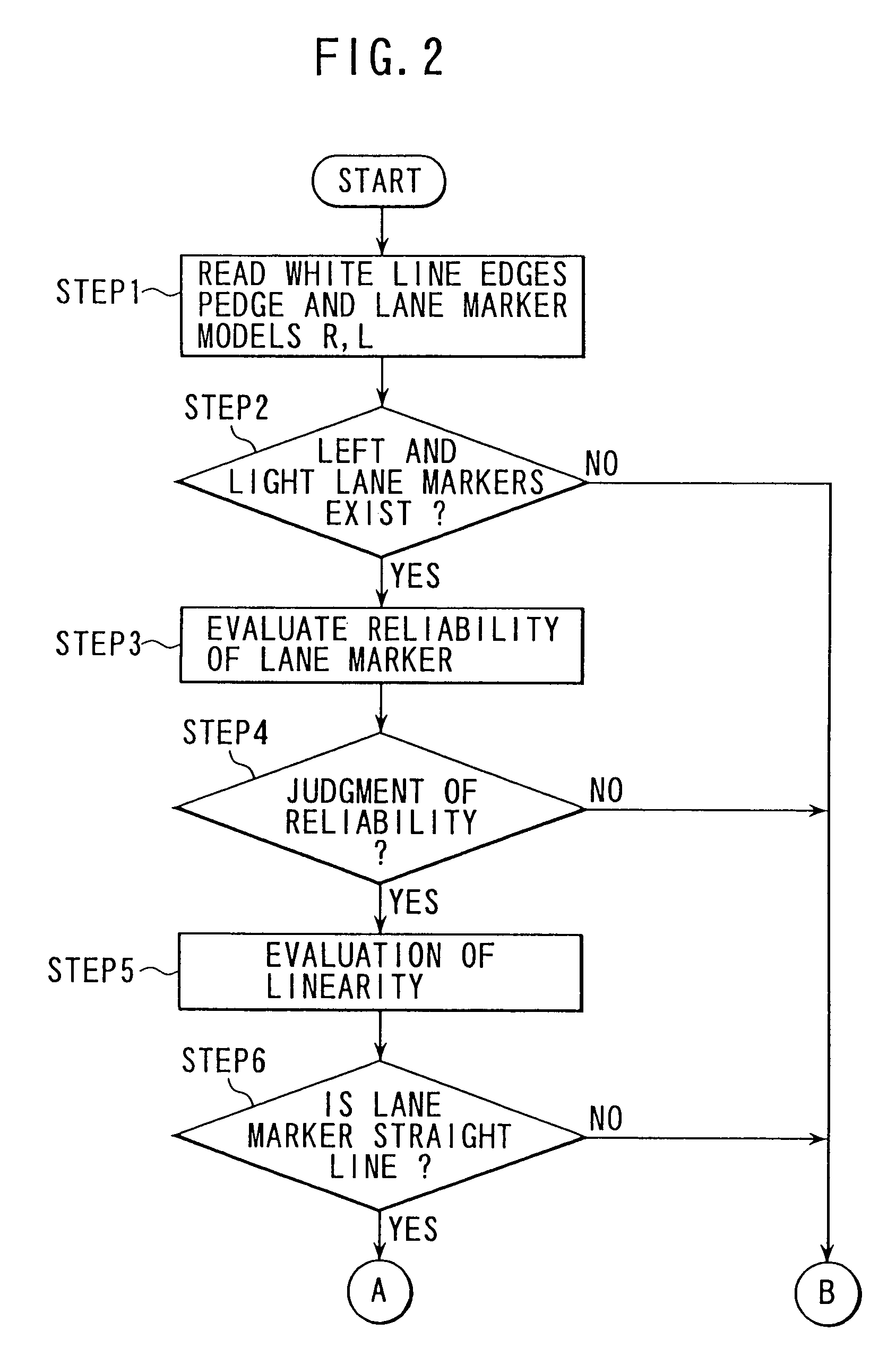
[0088]The steps of updating the affine parameter SHFT1 are the same as the flowcharts shown in FIGS. 2 and 3 in the first embodiment. What differs from the first embodiment is a step 11 of FIG. 3 conce...

fourth embodiment

[0093]This embodiment relates to the method of regulating the established vanishing point V (IV, JV) used in the transformation formulas 3 and 4 for calculating coordinates (X, Y) showing the position of an object by utilizing the vanishing point V2d (IV2D, JV2D) which is shown in FIG. 13.

[0094]FIG. 14 is a block diagram showing a stereoscopic type vehicle surroundings monitoring apparatus according to a fourth embodiment. In the correction calculating section 13, the established vanishing point V(IV, JV) is updated based on the vanishing point V2d(IV2D, JV2D) in the reference image and the calculated vanishing point IV, JV is outputted to the recognition section 10. Except for this section, the block diagram is identical to that of FIG. 1. Therefore, identical reference numbers denoted in both embodiments are not described in detail.

[0095]Next, steps for updating the established vanishing point IV, JV will be described. First, according to the steps from the step 1 to the step 6 sh...


PUM


Abstract

A distance correcting apparatus of a surroundings monitoring system includes a stereo imaging means for stereoscopically taking a pair of images of a frontal scenery, a parallax calculating means for calculating a parallax based on the pair of images, a distance calculating means for calculating a distance to an object based on the parallax and a parameter for correcting distance, an approximation line calculating means for calculating a plurality of approximation lines extending in the distance direction in parallel with each other based on the images, a vanishing point calculating means for calculating a vanishing point of the images from a point of intersection of the approximation lines and a parameter correcting means for correcting the parameter based on the calculated vanishing point.

Description

BACKGROUND OF THE INVENTION[0001]1. Field of the Invention[0002]The present invention relates to a distance correcting apparatus of a surroundings monitoring system for correcting distance information containing errors caused by a positional deviation of a stereoscopic camera and to a vanishing point correcting apparatus of the system.[0003]2. Discussion of the Background Art[0004]In recent years, a stereoscopic surrounding monitoring apparatus using a pair of left and right cameras, that is, a stereoscopic camera, having solid image element like CCD mounted on a vehicle and the like has been watched by concerned engineers. To detect a distance to an object, first respective pixel blocks having coincidence of brightness are found in left and right images (stereo matching), then distance data are calculated according to the principle of triangulation from a parallax, namely a relative deviation amount, between both pixel blocks. Consequently, in order to calculate distance data with ...

Claims


Application Information

Patent Timeline
IPC IPC(8): G06K9/00G01B11/00B60R21/00B60W30/00G01C3/06G06T1/00G06T7/60G08G1/16H04N13/00
CPCG06K9/00798G06T7/002H04N13/0025G06K9/00805H04N13/0246H04N13/025H04N13/0239G06T2207/10012H04N13/0011H04N13/0055H04N13/0296H04N2013/0081H04N2013/0092H04N2013/0096G06T7/85H04N13/189H04N13/246H04N13/111H04N13/296H04N13/239H04N13/25H04N13/133G06V20/588G06V20/58
Inventor SETA, ITARUHANAWA, KEIJI
Owner SUBARU CORP
Why Eureka
Try Eureka