
Side thruster valve and side thruster device

a technology of side thruster valve and side thruster, which is applied in the direction of rocket engine plants, machines/engines, jet propulsion plants, etc., can solve the problems of large device size and inability to reduce the combustion speed for improving fuel consumption, so as to improve fuel consumption and reduce the combustion gas pressure , the effect of lowering the combustion speed of solid propellan

Inactive Publication Date: 2006-01-17
MITSUBISHI HEAVY IND LTD
View PDF15 Cites 23 Cited by
  • Summary
  • Abstract
  • Description
  • Claims
  • Application Information

AI Technical Summary

Benefits of technology

[0015]In order to solve the abovementioned problems in the prior art side thruster valve, it is an object of the present invention to provide a side thruster valve in which a required torque of an actuating means including a drive unit, such as a servo-motor, needed for opening and closing the nozzle is reduced to thereby realize a compact and light weight device. Also, it is another object of the present invention to provide a side thruster device in which a plurality of the mentioned compact and light weight side thruster valves are provided independently of each other to thereby broaden a freedom of combustion control and improve the fuel consumption.
[0019]That is, according to the second means, in order to move the valve plug to the fully opened position or the fully closed position, the actuating means and the spring as the elastic member cooperate with each other. The spring is set to its natural length at the neutral position of the valve plug, so that the valve plug is activated to move to the neutral position from the fully opened position or the fully closed position. Thus, in the opening and closing of the valve plug, the function of the actuating means is largely assisted by the spring force and the required torque of the actuating means including a drive unit, such as a servo-motor, is reduced and a compact and light weight device can be realized.
[0021]That is, according to the third means, the combustion gas acts on one side of the piston that is constructed integrally and coaxially with the valve plug and is supplied via the orifice into the cylinder chamber that is formed on the other side of the piston. When the combustion gas pressure on the one side and the back pressure in the cylinder chamber on the other side are balanced with each other, the spring force that activates the valve plug to the closing side is added to the valve plug so that the valve plug is closed. Also, when the control device that controls the cylinder chamber to open into the atmosphere is operated, the balance of the combustion gas pressure and the back pressure in the cylinder chamber is released and thereby the valve plug is moved to the opening side. Thus, by using the control device, such as a simple actuator, the back pressure in the cylinder chamber is controlled so as to open and close the valve plug and a compact and light weight device can be easily realized.
[0023]That is, according to the fourth means, in the side thruster device, the side thruster valve made in the compact and light weight form by any one of the first to the third means is provided in the number of plural pieces. These side thruster valves are arranged independently of each other at the symmetrical positions relative to the axis of the aerospace craft. Hence, the plurality of side thruster valves are individually controllable and, if no thrust is needed, all of the plurality of side thruster valves are fully opened to thereby lower the combustion gas pressure, so that the combustion speed of the solid propellant is lowered and the fuel consumption can be improved.

Problems solved by technology

Hence, in order to realize a quick response by reducing the thrust change-over time, there is inevitably required a high torque of the servo-motor, which leads to a large size of the device.
Hence, in the combustion using solid propellant, there arises a problem that such a combustion control that, when no thrust is needed, all the nozzles are opened to thereby reduce the combustion gas pressure of the solid propellant and to reduce the combustion speed for improving the fuel consumption cannot be done.

Method used


Image

  • Side thruster valve and side thruster device
  • Side thruster valve and side thruster device
  • Side thruster valve and side thruster device

Examples


first embodiment

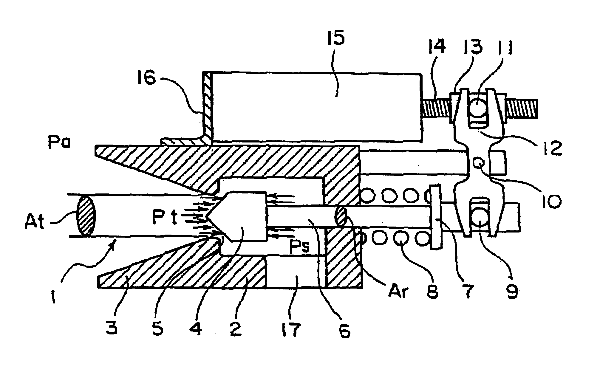
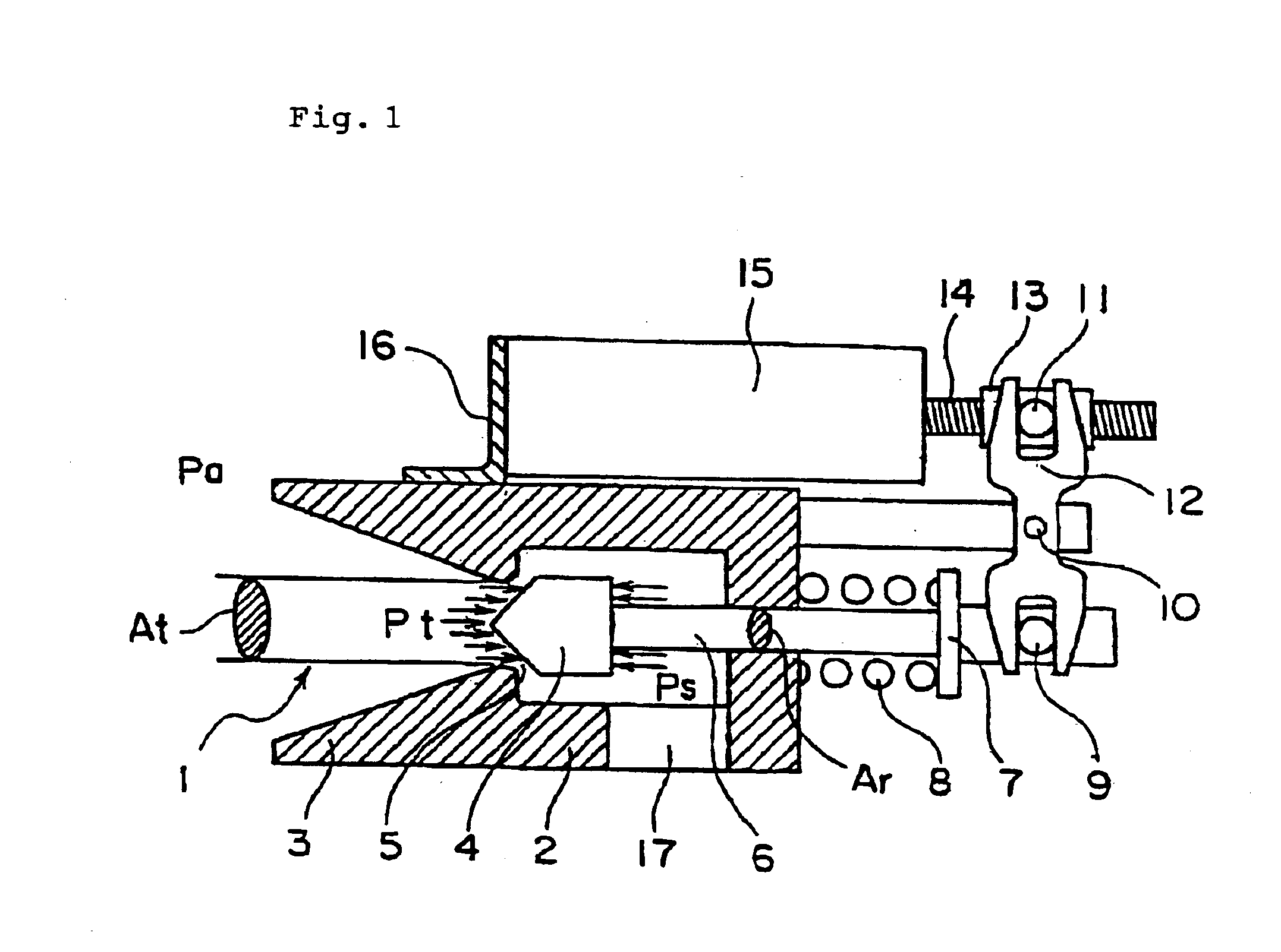
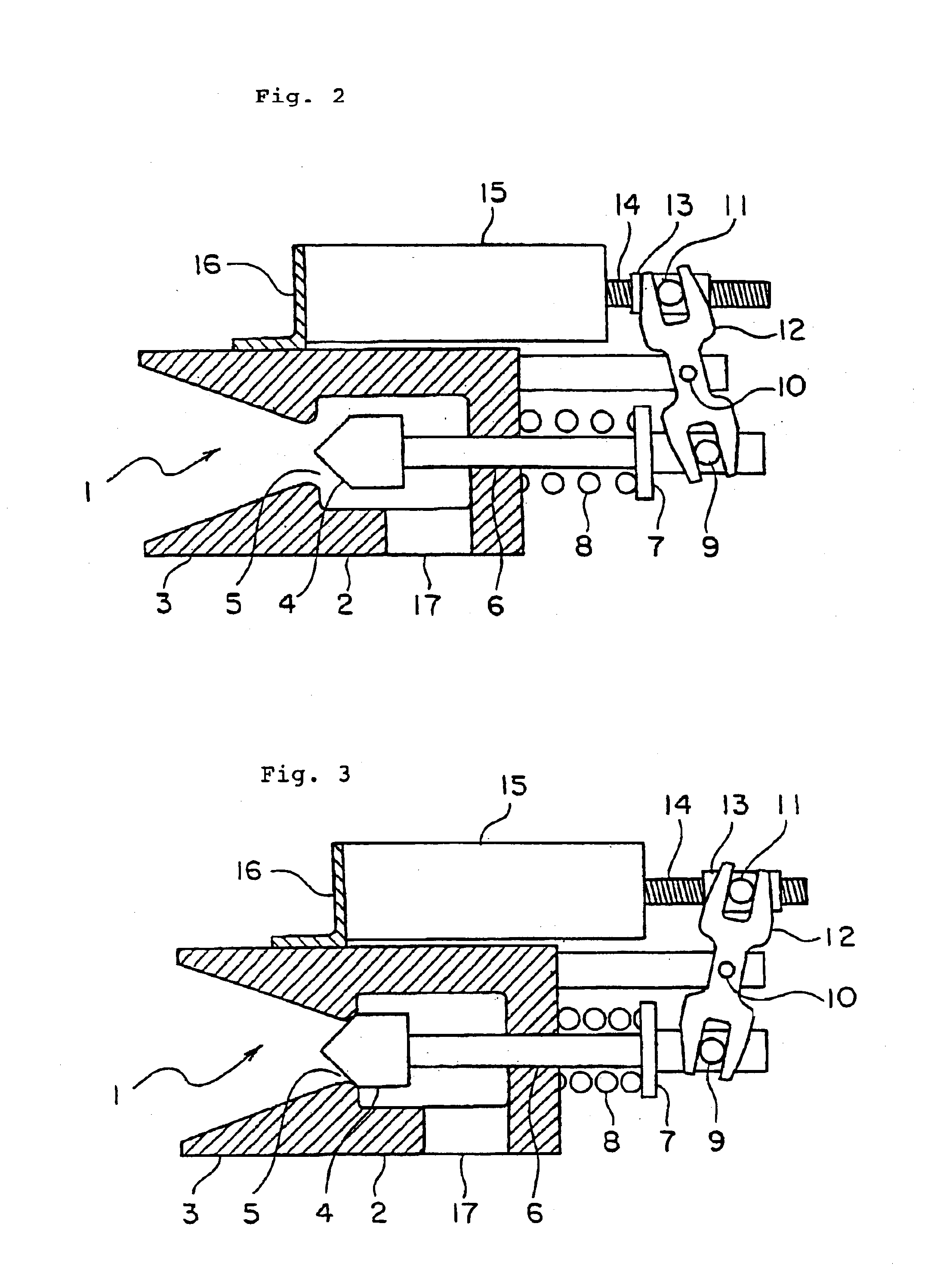
[0037]In the present first embodiment, numeral 1 designates a nozzle, that is constructed within a housing 2 as a main component part in combination with a nozzle skirt 3, a valve plug 4, etc.

[0038]That is, the valve plug 4 is provided on the combustion gas upstream side of the nozzle skirt 3. Combustion gas is supplied from a supply port 17 provided on one side of the valve plug 4 to be jetted through a gap between the portion of a nozzle throat 5 and the valve plug 4. Thereby, the thrust is generated by jetting of the combustion gas from the nozzle 1.

[0039]The valve plug 4 is connected to a shaft 6 and the shaft 6 slidably passes through the housing 2. By the flow path area of the nozzle throat 5 being made continuously changeable, the size of the thrust is made continuously controllable.

[0040]A spring seat 7 is fitted to the shaft 6 at the shaft end on the other side of the valve plug 4 and a spring 8 is provided between the housing 2 and the spring seat 7. The spring 8 is select...

second embodiment

[0059]In the present second embodiment, numeral 101 designates a nozzle, that is constructed as a main component part in combination with a cylinder 102, a nozzle skirt 103 formed at the front end of the cylinder 102, a valve plug 104, etc.

[0060]That is, the valve plug 104 is provided on the combustion gas upstream side of the nozzle skirt 103. Combustion gas is supplied from a supply port 106 provided on one side of the valve plug 104 to be jetted through a gap between the portion of a nozzle throat 105 and the valve plug 104. Thereby, the thrust is generated by jetting of the combustion gas from the nozzle 101.

[0061]The valve plug 104 at its central portion is integrally and coaxially connected with a piston 114. The piston 114 at its one side surface receives combustion gas supply pressure Ps supplied from a supply port 106 so that the piston 114 is slidable in the valve plug axial direction within the cylinder 102. By this sliding motion, the flow path area of the nozzle throat ...


PUM


Abstract

A side thruster valve of an aerospace craft is improved to reduce torque of a servo-motor, etc. needed for nozzle opening and closing to thereby realize a compact and light weight device. The side thruster valve comprises a valve plug having its back directed to an axis of the aerospace craft and independently movable between a fully opened position and a fully closed position of the valve plug in a plane orthogonal to the axis of the aerospace craft, an actuating means for moving the valve plug in an axial direction of the valve plug and an elastic member for activating the valve plug in the axial direction of the valve plug. In a side thruster device comprising a plurality of the side thruster valves, the side thruster valves are arranged independently of each other to thereby broaden freedom of combustion control and improve fuel consumption.

Description

TECHNICAL FIELDField of the Invention[0001]The present invention relates to a side thruster valve for performing motion control of an aerospace craft by using solid propellant and also relates to a side thruster device using this side thruster valve.DESCRIPTION OF THE PRIOR ART[0002]A prior art side thruster valve that performs motion control of an aerospace craft can be basically separated into two types, that is, one in which a plurality of respectively independent side thruster valves are arranged and the other in which two valves having their backs connected to each other are arranged symmetrically relative to a central axis of the aerospace craft so that the valves are opened on one side and closed on the other side by a common shaft having valve plugs. Here, as one example of the prior art side thruster valve, the latter type will be outlined with reference to FIG. 11.[0003]FIG. 11 is a cross sectional view showing one example of a side thruster valve used in a prior art side ...

Claims


Application Information

Patent Timeline
IPC IPC(8): F02K1/18F02K9/32F02K9/44F02K9/88F02K9/92
CPCF02K9/32F02K9/92F02K9/88F02K9/44
Inventor FUJITA, TOSHIHARU
Owner MITSUBISHI HEAVY IND LTD
Learn More