Force measuring device, in particular for seat weight determination in a motor vehicle

a technology of force measurement and seat weight, which is applied in the direction of force/torque/work measurement apparatus, instruments, pedestrian/occupant safety arrangement, etc., can solve the problems of high cost of correct balancing of measuring system and its mounting in the taking up element, and achieve simple and relatively accurate mounting process, high deformation, and high accuracy

Inactive Publication Date: 2006-01-17
ROBERT BOSCH GMBH
View PDF9 Cites 13 Cited by
  • Summary
  • Abstract
  • Description
  • Claims
  • Application Information

AI Technical Summary

Benefits of technology

[0007]In accordance with another embodiment of the present invention, with the magnetic field-sensitive sensor when the force-loaded taking up element is not loaded, it is arranged in alignment with the pole axis of the magnet. This provides the advantage that the zero point over the service life of the force measuring device has a relatively high accuracy since the aging as well as temperature dependency both of the permanent magnets and also the magnet yokes do not act negatively on a drift of the zero point. Moreover, this arrangement a polarity-sign accurate detection of the magnetic field and therefore also a force direction detection.
[0008]In accordance with a preferable embodiment of the present invention, the bar-shaped element is arranged on the taking up element and mounted in the region of the stationary bearing point. Thereby it is possible to introduce the measuring device as a relatively short unit from the other bearing point into the taking up element, so that a very simple and relatively accurate mounting process is utilized.
[0009]In accordance with a further preferable embodiment of the invention, the taking up element is formed as a rotation-symmetrical component. The first receptacle is formed as a throughgoing passage arranged perpendicular to the axis of symmetry, so that with respect to the first receptacle two connecting webs which extend parallel to one another are provided and connect the bearing points with one another. With this construction an especially high deformation and therefore a sensitivity of the force measuring device is possible when a force is applied perpendicular to the longitudinal axis of the taking up element.

Problems solved by technology

Because of the separate arrangement of the magnet and the magnetic field-sensitive sensor element, the correct balancing of the measuring system as well as its mounting in the taking up element are relatively expensive.

Method used


Image

  • Force measuring device, in particular for seat weight determination in a motor vehicle
  • Force measuring device, in particular for seat weight determination in a motor vehicle
  • Force measuring device, in particular for seat weight determination in a motor vehicle

Examples


Embodiment Construction

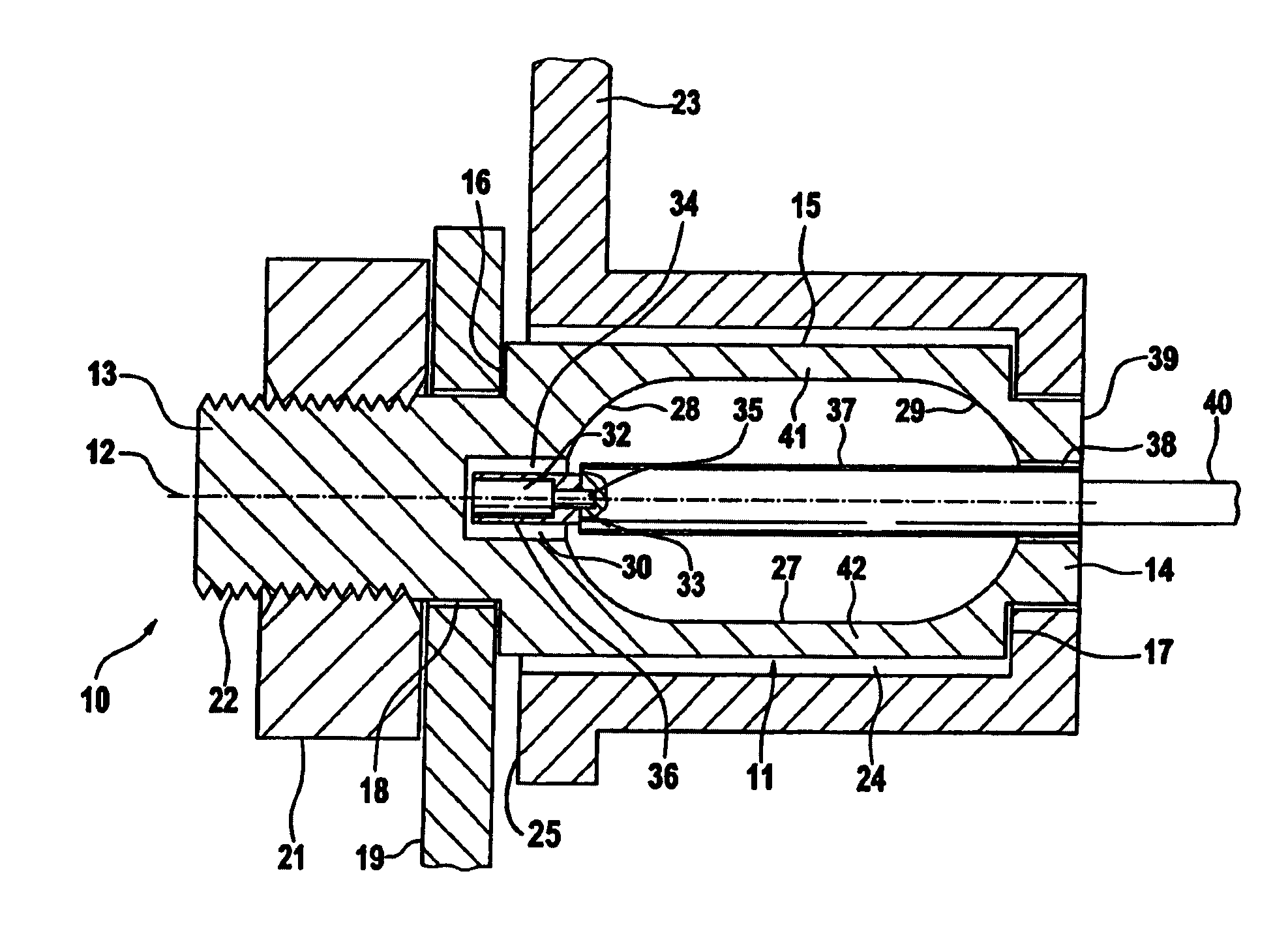
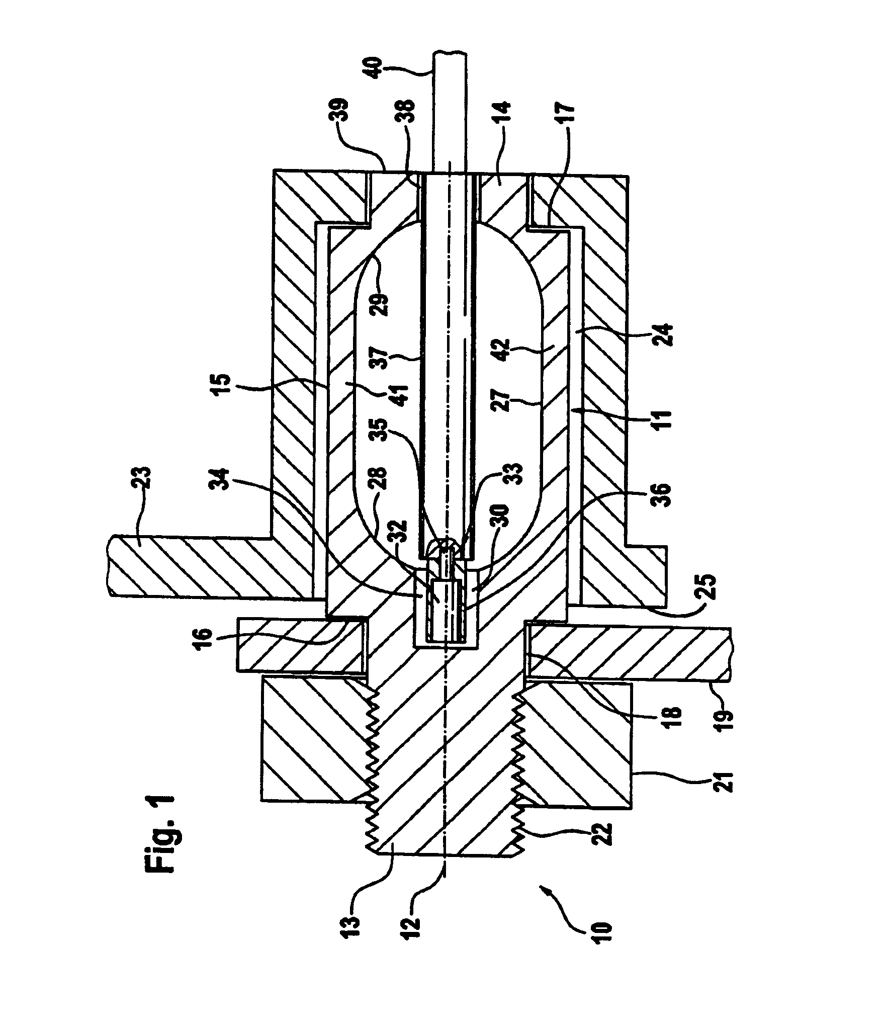
[0013]A force measuring device shown in FIG. 1 is identified as a whole with reference numeral 10 and is used for a seat weight determination in a motor vehicle. Such a seat weight determination is required in modern motor vehicles for example for correctly controlling the timely process of a seat belt course as well as the airbag release.

[0014]The force measuring device 10 has a bearing body 11 which is formed as a rotation-symmetrical component with a longitudinal axis 13. The bearing body 11 is composed of a ferromagnetic material and has at its opposite sides end portions 13 and 14 with a diameter which is smaller than the diameter of a central portion 15. Shoulders 16 and 17 are formed between the end portions 13, 14 and the central portion 15. They serve as abutments.

[0015]The bearing body 11 is inserted with its end portion 13 into an opening 18 of a seat rail 19 which serves as a stationary bearing. The bearing body 11 can be fixed rigidly on the seat rail 19 by a nut 21 whi...


PUM

PropertyMeasurementUnit
seat weightaaaaaaaaaa
forceaaaaaaaaaa
diameteraaaaaaaaaa

Abstract

A force measuring device for seat weight determination in a motor vehicle includes a taking up element which has at least two bearing points. The device further includes a mechanism forming a first recess in the taking up element in a region between at least two bearing points and a rod-shaped element which extends in the longitudinal axis of the taking up element and is not loaded by bending forces. The rod-shaped element has a free end which deviates from the longitudinal axis of the taking up element when a force to be measured acts on the taking up element, and a measuring unit with a magnet and a magnetic field-sensitive sensor The magnet and the magnetic field-sensitive sensor are arranged immovably relative to one another so that the distance from the magnet to a ferromagnetic material changes under loading with the force.

Description

BACKGROUND OF THE INVENTION[0001]The present invention relates to a force measuring device, in particular for seat weight determination in a motor vehicle.[0002]Force sensors of the above mentioned general type are known in the art. One of such force sensors is disclosed in the German patent document DE 35 15 126 A1. In this force sensor shown in FIG. 2 a magnet is arranged at a free end of the bar-shaped element, whose position changes in response to an exterior loading of the taking up element relative to a magnetic field-sensitive sensor element, and the sensor element is arranged immovably in the region of a bearing point of the taking up element. Because of the separate arrangement of the magnet and the magnetic field-sensitive sensor element, the correct balancing of the measuring system as well as its mounting in the taking up element are relatively expensive.SUMMARY OF THE INVENTION[0003]Accordingly, it is an object of the present invention to provide a force measuring devic...

Claims


Application Information

Patent Timeline
Patent Type & Authority Patents(United States)
IPC IPC(8): G01L1/26G01L5/04B60N2/00G01G3/15B60N2/90B60R21/01B60R21/015G01G7/02G01G19/12G01G19/414G01G19/52G01L1/04G01L1/14
CPCB60N2/002G01G7/02B60R21/01516G01L1/044G01L1/14G01G19/4142
Inventor DUKART, ANTON
Owner ROBERT BOSCH GMBH
Why Eureka
Try Eureka