VTOL aircraft external load drag reduction system

a drag reduction and aircraft technology, applied in the field of vertical takeoff and landing aircraft, can solve the problems of many external loads that cannot tolerate the air load created, the 53e the external load would be so large that it would not fit in the hangar deck or on the elevator of an lha or lhd, etc., to achieve the effect of reducing drag and air

Inactive Publication Date: 2006-01-17
SIKORSKY AIRCRAFT CORP
View PDF17 Cites 9 Cited by
  • Summary
  • Abstract
  • Description
  • Claims
  • Application Information

AI Technical Summary

Benefits of technology

[0007]The drag reduction system according to the present invention extends from an underside of a VTOL aircraft forward of a four-point sling system. The four-point sling system carries an external load close to or in contact with the underside of the airframe and oriented along the aircraft longitudinal axis. The drag reduction system reduces drag and air loads on the external load. The drag reduction system includes a retractable shield mounted to the aircraft such that attachment / detachment problems as well as inventory issues are avoided.
[0008]The present invention therefore provides a drag reduction and airloads reduction system for VTOL aircraft externally slung loads which permits higher cruise speeds and longer ranges.

Problems solved by technology

Thus, a conventional helicopter like the CH-53E would be so large that it would not fit in the hangar deck or on the elevator of an LHA or LHD.
Disadvantageously, this configuration results in high aircraft drag due to the addition of the non-aerodynamic load beneath the aircraft.
Furthermore many external loads cannot tolerate the air loads created at typical aircraft cruise speeds of around 150 kts.
This further limits aircraft cruise speed and degrades range capability.
Disadvantages with this approach include the necessity of maintaining a relatively large inventory of fairings as each fairing is particularly tailored for a particular load.
The fairings must also be attached and removed from the external load, which increases deployment times. Aerodynamic forces created by fairings may also be unfavorable to a slung load resulting in undesirable swinging.
Attaching a device to a helicopter to fair around a slung load may also be impractical because the external loads are typically slung a relatively long distance from the aircraft underside.

Method used


Image

  • VTOL aircraft external load drag reduction system
  • VTOL aircraft external load drag reduction system
  • VTOL aircraft external load drag reduction system

Examples


Embodiment Construction

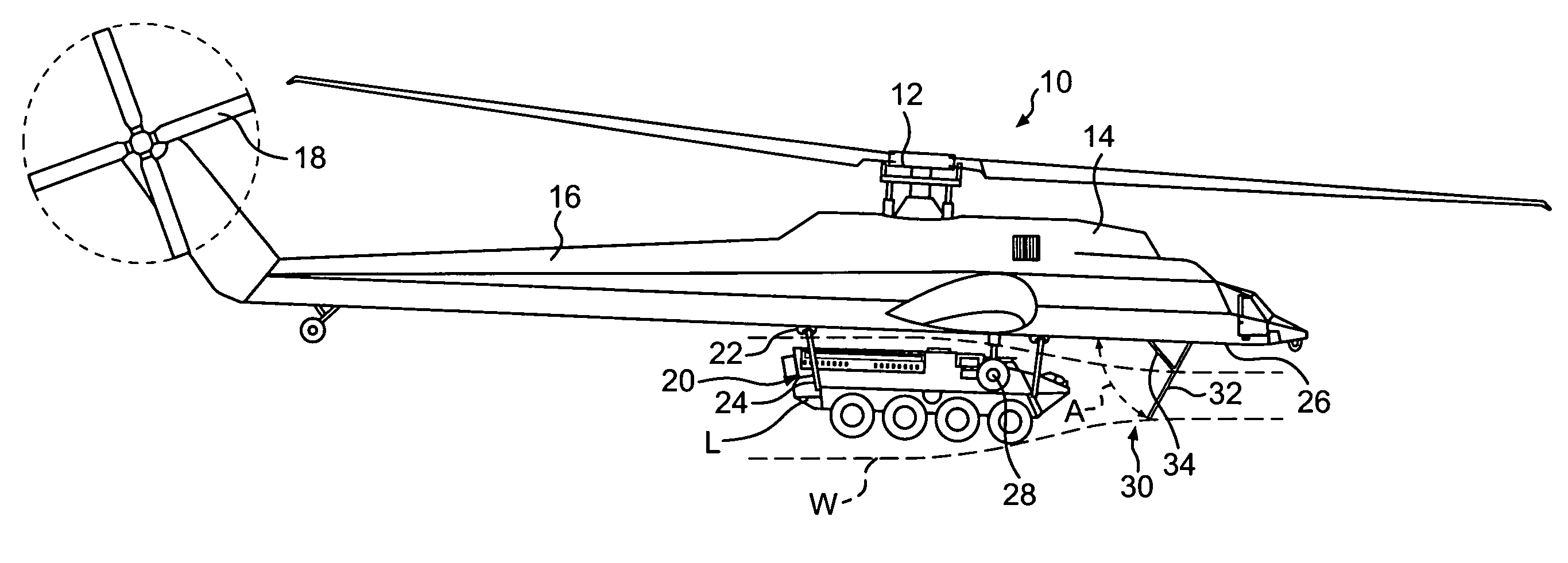
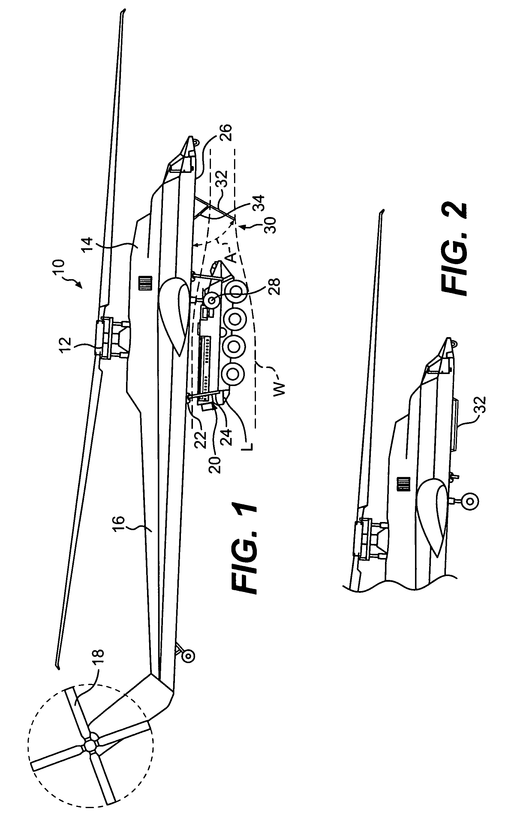
[0014]FIG. 1 schematically illustrates a VTOL aircraft 10 having a main rotor assembly 12. The aircraft 10 includes an airframe 14 having an extending tail 16 which mounts an anti-torque rotor 18. Although a particular flying crane type helicopter configuration, which does not include a cabin section, is illustrated in the disclosed embodiment, other VTOL machines such as tandem rotor, coaxial rotor, tilt-rotor and tilt-wing aircraft will also benefit from the present invention.

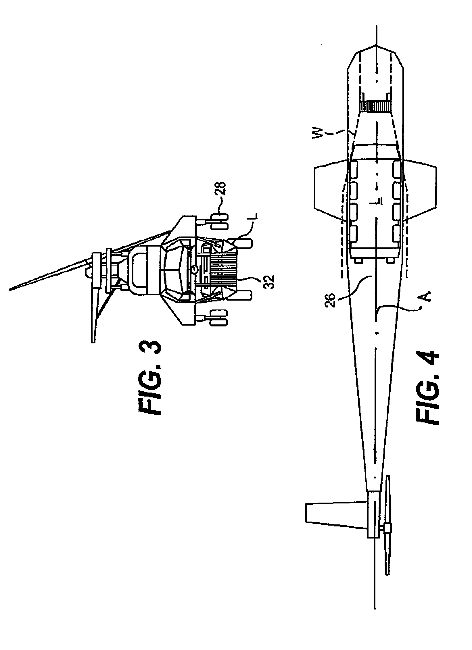
[0015]An external load L is attached to the airframe 14 through a four-point sling system 20. The sling system 20 includes four hoists 22 which deploy a cable 24 to each corner of the external load L for attachment thereof. It should be understood that various sling actuation and mounting arrangements will also benefit from the present invention. The cables 24 are connected to the load L in a conventional manner. The four-point sling system 20 preferably retracts the external load L to be carried close to or ...


PUM


Abstract

A drag reduction system extends from an underside of a VTOL aircraft forward of a four-point sling system. The four-point sling system carries an external load close to an underside of the airframe and oriented along the aircraft longitudinal axis. The drag reduction system includes a retractable shield mounted beneath the underside of the aircraft which reduces drag of the external sling load and reduces the airloads on the external load.

Description

BACKGROUND OF THE INVENTION[0001]The present invention relates to a vertical takeoff and landing (VTOL) aircraft, and more particularly to a drag reduction system for an external load carried thereby.[0002]Future military forces require enhanced vertical lift capabilities in a compact package. The CH-53E is currently the world's largest shipboard compatible helicopter. A significant consideration in the design of the CH-53E was shipboard compatibility. The CH-53E effectively defines the maximum aircraft spatial capacity, which will fit on the elevators and in the hangar deck of United States Marine Corps Amphibious Assault Ships, more commonly called an LHA or LHD. Emerging payload weight requirements are beyond the growth capabilities of the CH-53E while maintaining current shipboard compatibility requirements. Thus, a conventional helicopter like the CH-53E would be so large that it would not fit in the hangar deck or on the elevator of an LHA or LHD.[0003]Super heavy lift (SHL) V...

Claims


Application Information

Patent Timeline
Patent Type & Authority Patents(United States)
IPC IPC(8): B64C1/20B64C1/22B64C7/00B64D1/22
CPCB64D1/22B64C7/00
Inventor SCOTT, MARK WINFIELD
Owner SIKORSKY AIRCRAFT CORP
Why Eureka
Try Eureka