Projector

a projector and projector technology, applied in the field of projectors, can solve the problems of inability to quickly dissipate heat, increase the heat generated in the polarization plate on the exit side, etc., and achieve the effects of fast cooling, improved cooling capability, and smooth cooling of the optical modulation system

Inactive Publication Date: 2006-01-17
SEIKO EPSON CORP
View PDF4 Cites 19 Cited by
  • Summary
  • Abstract
  • Description
  • Claims
  • Application Information

AI Technical Summary

Benefits of technology

[0007]In order to solve the problems, it is conceivable that improvement in cooling efficiency is facilitated by increasing the number of rotation of the cooling fan and the mounted number of cooling fans. However, it is necessary to make the size and the mounted number of cooling fans as small as possible for realizing miniaturization and lower noise of the projector.
[0023]In an aspect of the invention, it is preferred that the projector further includes an exterior housing for accommodating the optical modulation systems, the color composition optical system, and the projection optical system, wherein the number of the cooling fans is set to two, and air intake ports of these cooling fans are formed on two different surfaces of the exterior housing. According to the invention, since the cooling air outside the projector is introduced into the respective cooling fans from the two different surfaces of the exterior housing, the cooling air can be introduced into the optical modulation systems smoothly to further improve cooling efficiency.

Problems solved by technology

In addition, recently, a projector of higher intensity is requested, however, by the above described structure, there is a possibility that the amount of heat generated in the polarization plate on the exit side is especially increased, and the heat cannot be dissipated quickly.
However, it is necessary to make the size and the mounted number of cooling fans as small as possible for realizing miniaturization and lower noise of the projector.

Method used


Image

  • Projector
  • Projector
  • Projector

Examples


Embodiment Construction

[0031]Hereinafter, one exemplary embodiment of the invention will be described by referring to the drawings.

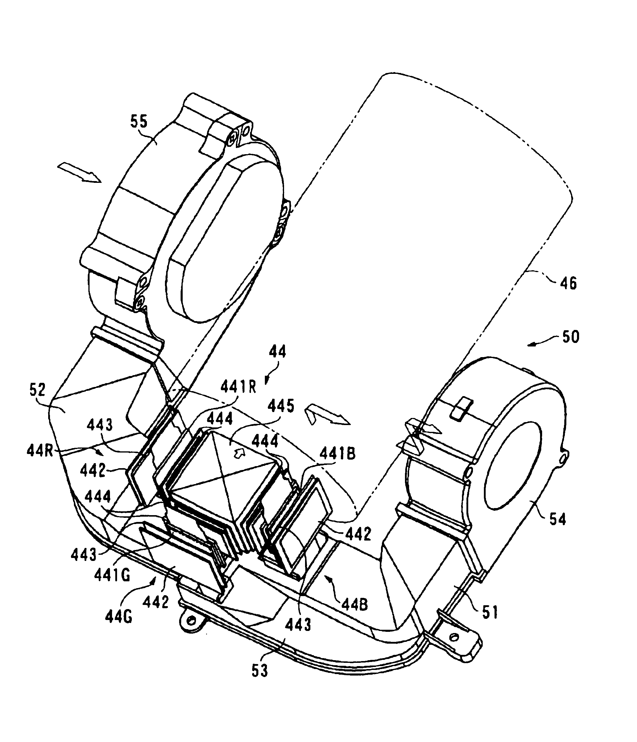
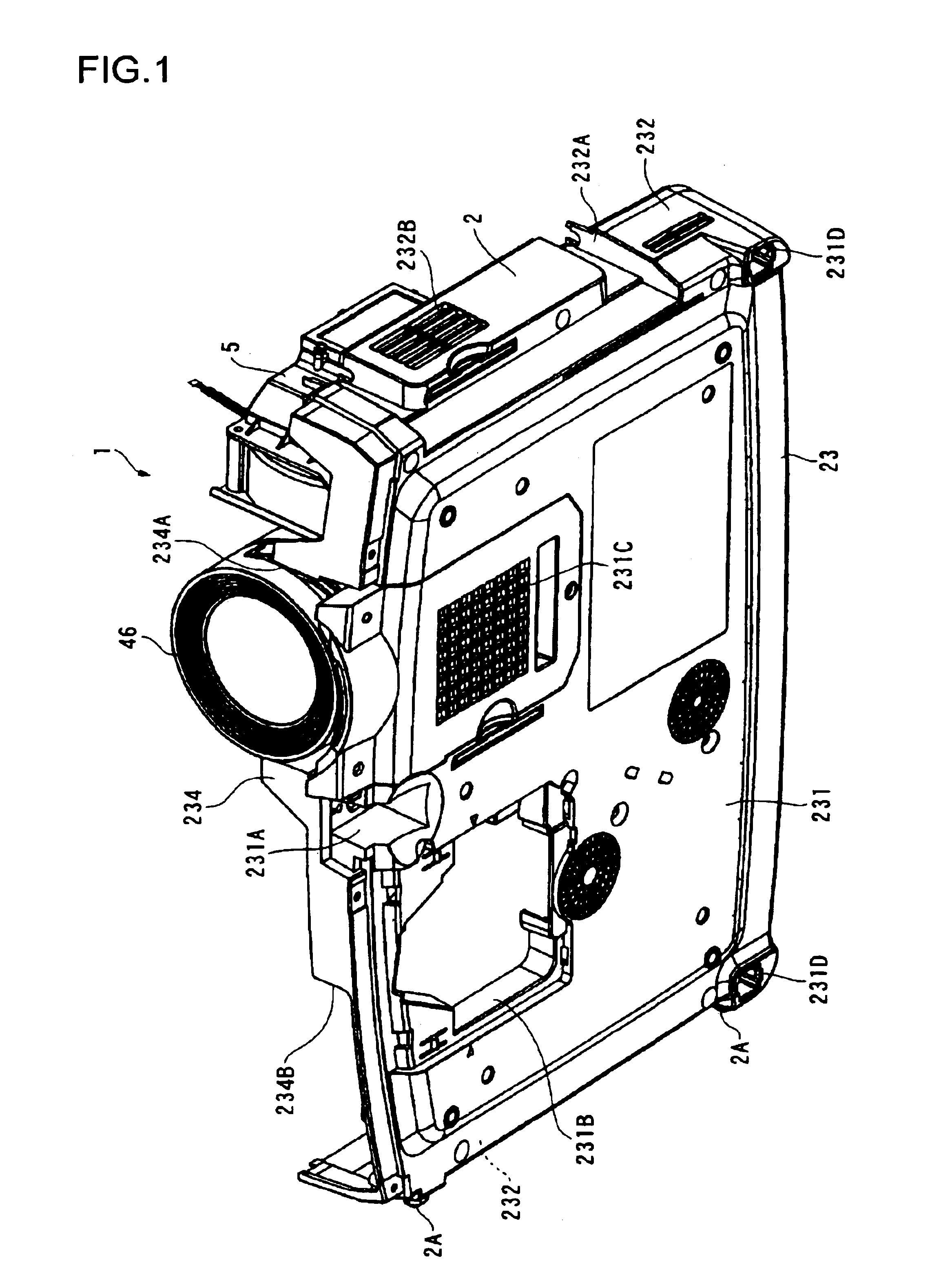
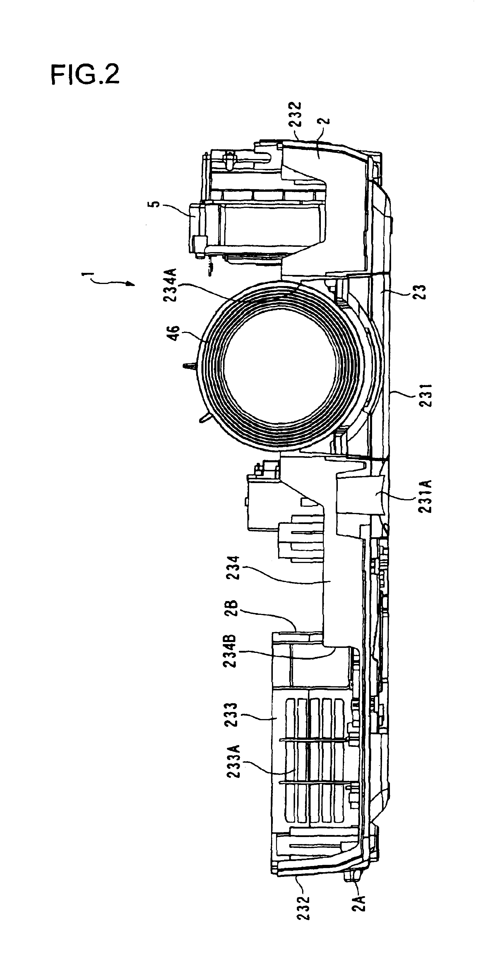
[0032]FIG. 1 is a perspective view from below of a projector 1 according to the exemplary embodiment. Specifically, the drawing shows that a projection lens 46 and an internal cooling unit 5 are mounted to a lower case 23 of the projector 1. FIG. 2 is a front view of the projector 1 in the condition of FIG. 1. FIG. 3 is a plan view schematically showing an optical system within an optical unit 4. Note that these components 4, 5, 23, and 46 constituting the projector will be described later in detail.

[0033]In FIGS. 1 to 3, the projector 1 can include an exterior case 2 as an exterior housing, a power supply unit (not shown) accommodated within the exterior case 2, the optical unit 4 arranged in the U-shape similarly disposed within the exterior case 2, and the internal cooling unit 5 similarly disposed within the exterior case 2, and has the form of a substantially rectangular ...


PUM

PropertyMeasurementUnit
luminous fluxaaaaaaaaaa
color compositionaaaaaaaaaa
optical propertiesaaaaaaaaaa

Abstract

An aspect of the invention provides a duct capable of cooling optical modulation systems with high efficiency while realizing miniaturization and reduction of the mounted number of cooling fans. The duct can be used for a projector including plural optical modulation systems, a dichroic prism, and a projection lens, and the respective optical modulation systems include liquid crystal panels, entrance side polarization plates, viewing angle correction plates, and exit side polarization plates. The duct can have plural air guide paths through which cooling air passes, a discharge opening, entrance side discharge openings, and exit side discharge openings formed in these air guide paths. With the optical modulation systems as targets of independent cooling, the entrance side discharge openings and the exit side discharge openings with respect to the targets of independent cooling are formed in different air guide paths.

Description

BACKGROUND OF THE INVENTION[0001]1. Field of Invention[0002]An aspect of the invention relates to a duct used for a projector including, for example, plural optical modulation systems for modulating plural color lights with respect to each color light according to image information to form optical images, a color composition optical system for combining the optical images modulated in the respective optical modulation systems, and a projection optical system for magnification projection of the composite optical image, and for introducing cooling air to the optical modulation systems, a cooling device, and a projector.[0003]2. Description of Related Art[0004]Conventionally, using a projector for a presentation in a conference, an academic conference, an exhibition, and the like is well known. Some of such projectors adopt the so-called three-plate system in which luminous flux emitted from a light source device is separated into light of three primary colors of red, green, and blue b...

Claims


Application Information

Patent Timeline
Patent Type & Authority Patents(United States)
IPC IPC(8): G03B21/18G02F1/1335G03B21/22G03B21/26G02F1/13G03B21/00G03B21/16G03G21/16
CPCG03G21/206G03G2221/1645
Inventor KOBAYASHI, HIROSHI
Owner SEIKO EPSON CORP
Why Eureka
Try Eureka