Microfluidic controller and detector system with self-calibration

a microfluidic controller and detector system technology, applied in the direction of fluorescence/phosphorescence, machines/engines, diaphragms, etc., can solve the problems of large sample size, high space requirements for sampling and equipment, and current screening methods still have a number of associated problems

Inactive Publication Date: 2006-01-17
CAPLIPER LIFE SCI INC
View PDF18 Cites 27 Cited by
  • Summary
  • Abstract
  • Description
  • Claims
  • Application Information

AI Technical Summary

Benefits of technology

[0008]The present invention provides a microfluidic controller and detector system. The controller and detector system is typically configured to receive a fluidic chip including at least two intersecting channels. The system preferably includes a detection zone and a material direction system comprising an interface configured for contact with the at least two intersecting channels on a different side of an intersection formed by the at least two intersecting channels. The microfluidic controller and detector optionally further includes an optics block comprising an objective lens and is located within the housing adjacent the detection zone. Finally, the microfluidic controller and detector typically includes a control system coupled to the microfluidic controller and detector with a communication channel for controlling operation of the microfluidic controller and detector. The control system is configured for receiving and analyzing data from the optics block.

Problems solved by technology

Despite the improvements achieved using parallel screening methods and other technological advances, such as robotics and high throughput detection systems, current screening methods still have a number of associated problems.
For example, screening large numbers of samples using existing parallel screening methods have high space requirements to accommodate the samples and equipment, e.g., robotics etc., high costs associated with that equipment, and high reagent requirements necessary for performing the assays.
Additionally, in many cases, reaction volumes must be very small to account for the small amounts of the test compounds that are available.
Such small volumes compound errors associated with fluid handling and measurement, e.g., due to evaporation, small dispensing errors, or the like.
Additionally, fluid handling equipment and methods have typically been unable to handle these volume ranges within any acceptable level of accuracy due in part to surface tension effects in such small volumes.

Method used


Image

  • Microfluidic controller and detector system with self-calibration
  • Microfluidic controller and detector system with self-calibration
  • Microfluidic controller and detector system with self-calibration

Examples


Embodiment Construction

[0035]A microfluidic controller and detector with self-calibration are disclosed. The following description is presented to enable any person skilled in the art to make and use the invention. Descriptions of specific embodiments and applications are provided only as examples and various modifications will be readily apparent to those skilled in the art. The general principles defined herein can be applied to other embodiments and applications without departing from the spirit and scope of the invention. Thus, the present invention is to be accorded the widest scope encompassing numerous alternatives, modifications and equivalents consistent with the principles and features disclosed herein. For purpose of clarity, details relating to technical material that is known in the technical fields related to the invention have not been described in detail so as not to unnecessarily obscure the present invention.

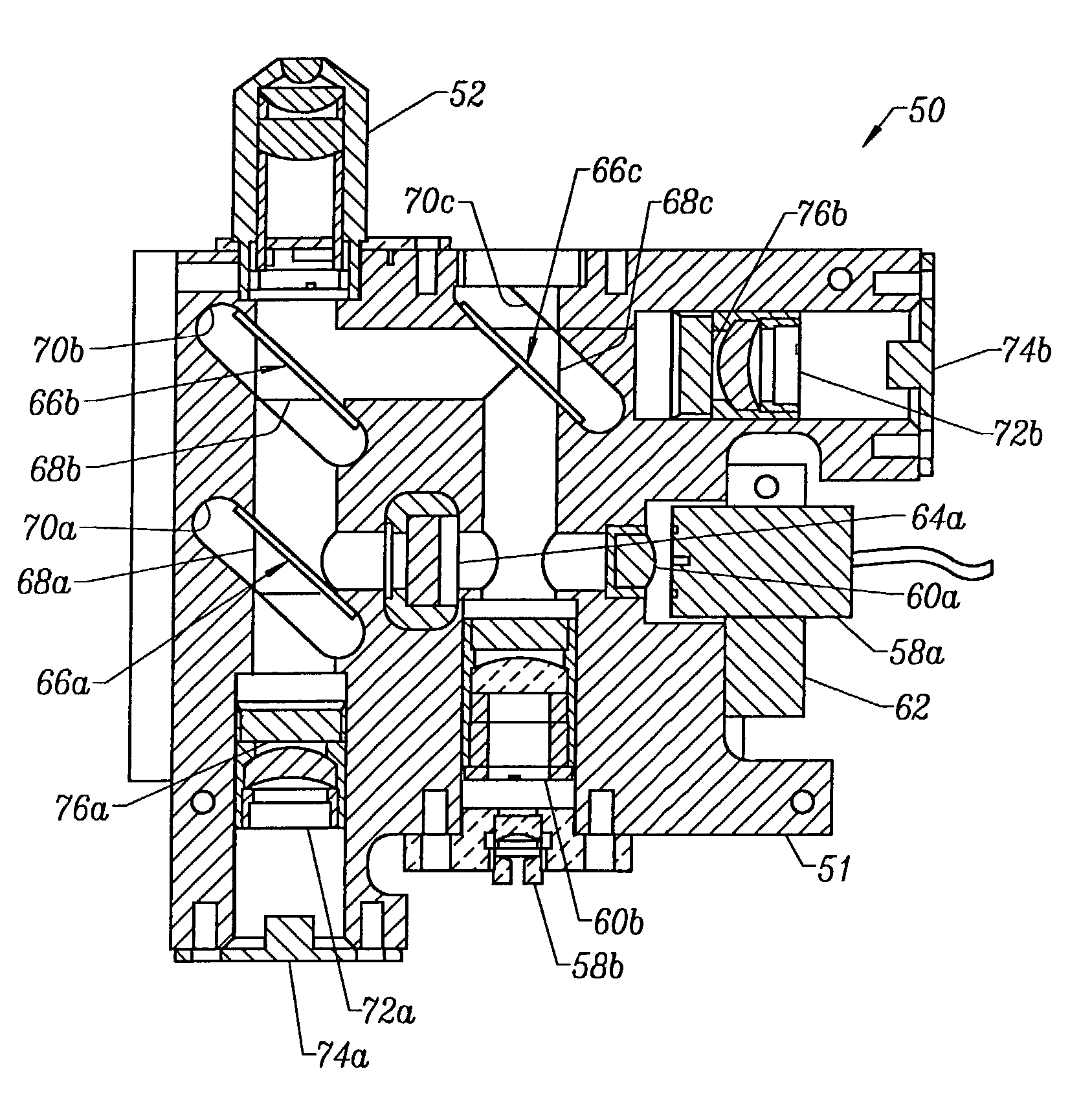
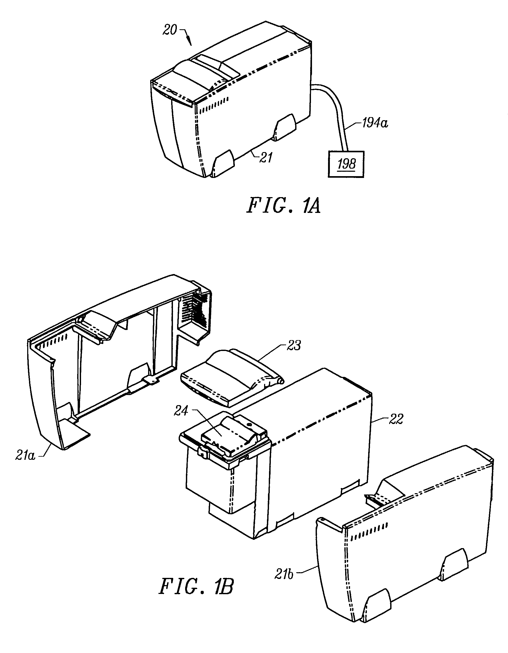
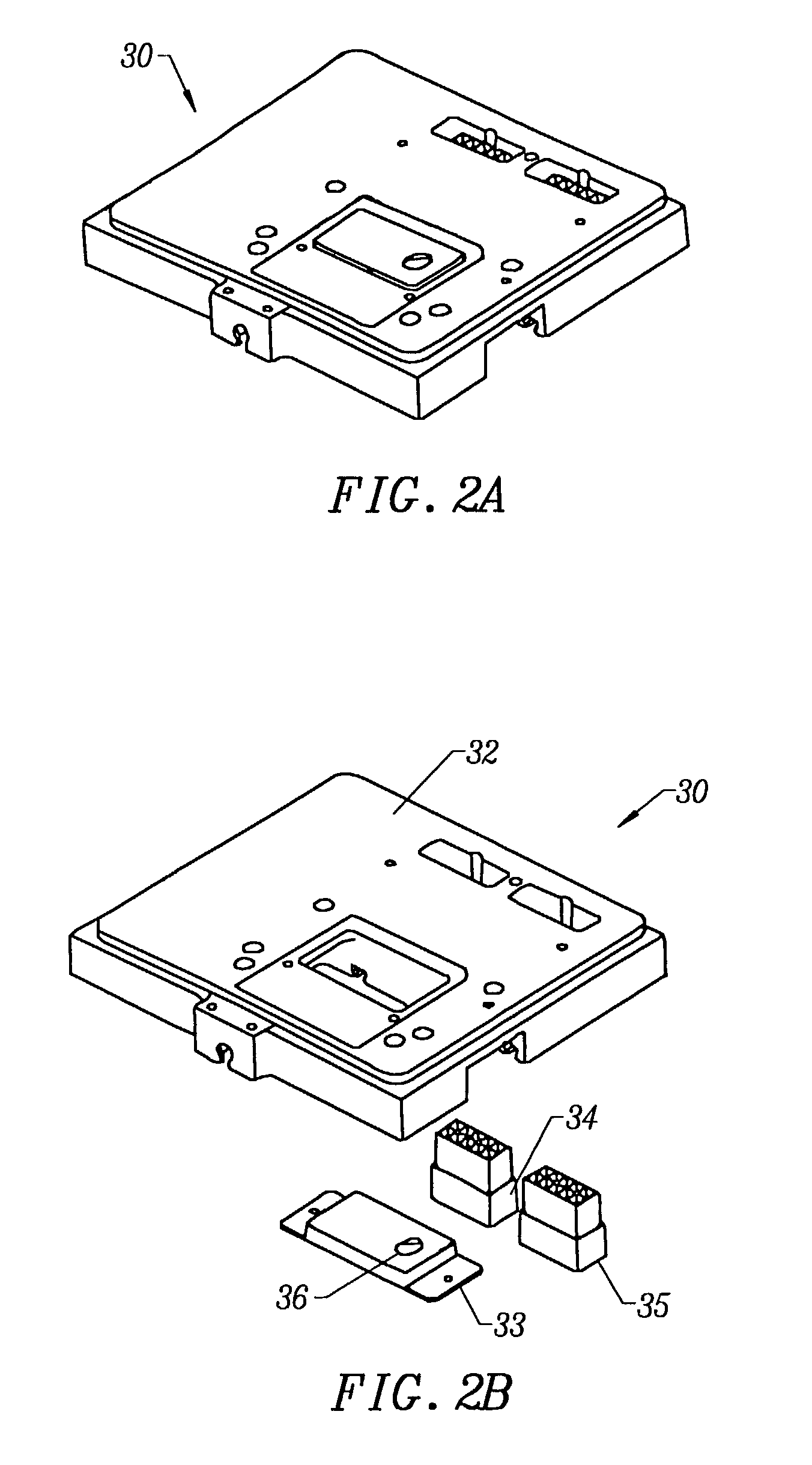
[0036]FIGS. 1A and 1B are a perspective view and an exploded perspective view, r...


PUM

PropertyMeasurementUnit
angle of incidenceaaaaaaaaaa
wavelengthaaaaaaaaaa

Abstract

A microfluidic controller and detector system and method for performing screening assays are disclosed. The microfluidic controller and detector system comprises a fluidic chip that includes at least two intersecting channels and a detection zone, a fluid direction system comprising an electrical interface configured for electrical contact with the at least two intersecting channels, an optics block having an objective lens disposed adjacent the detection zone, and a control system coupled to the optics block and adapted to receive and analyze data from the optics block. The electrical interface generally includes electrodes configured for electrical contact with the intersecting channels and coupled to electrode channels for supplying electrical input to the electrodes. A reference channel is optionally provided to calibrate the electrode channels.

Description

CROSS REFERENCE TO RELATED APPLICATION[0001]This application is a Divisional of U.S. patent application Ser. No. 09 / 374,878, filed on Aug. 13, 1999, now issued as U.S. Pat. No. 6,498,497 B1, which is hereby incorporated by reference for all purposes. This application also claims priority to U.S. Provisional Patent Application No. 60 / 104,260, filed on Oct. 14, 1998, now abandoned, which is hereby incorporated by reference for all purposes.BACKGROUND OF THE INVENTION[0002]The present invention relates to a controller and detector system for microfluidic systems, and more particularly, to a microfluidic controller and detector system for use with assay systems for performing chemical and biochemical analyses.[0003]Analysis of chemical and biochemical samples often requires detection and identification of the constituent elements of the sample. Microfluidic devices are often used to separate and control movement of the elements of the sample to detect a property of the elements with a d...

Claims


Application Information

Patent Timeline
Patent Type & Authority Patents(United States)
IPC IPC(8): G01N27/453G01N31/20B01L3/00B01L9/00G01N21/47G01N21/64G01N27/26G01N27/447G01N37/00
CPCB01L9/527G01N27/44791G01N27/44721B01L3/5027B01L2200/027B01L2400/0415B01L2200/148
Inventor CHOW, CALVIN Y. H.JENSEN, MORTEN J.KENNEDY, COLIN B.LACY, MICHAEL M.NAGLE, ROBERT E.
Owner CAPLIPER LIFE SCI INC
Why Eureka
Try Eureka