Method and apparatus for receiving a universal input voltage in a welding, plasma or heating power source

a technology of power source and input voltage, applied in the field of power sources, can solve the problems of power source failure or insufficient power, time-consuming, impersonal injury,

Inactive Publication Date: 2006-01-17
ILLINOIS TOOL WORKS INC
View PDF50 Cites 89 Cited by
  • Summary
  • Abstract
  • Description
  • Claims
  • Application Information

AI Technical Summary

Benefits of technology

[0024]The second magnitude is greater than the control power magnitude, and/or converting the dc second signal into control power includes buck converting the dc second signal in additional alternative.
[0025]According to a third aspect of the invention a welding type power source capable of receiving a range of input voltages and frequencies includes a de bus. An output circuit receives the dc bus, and provides a welding type output power signal. The output power is voltage and frequency independent of the input power. A controller is connected to the output circuit. Power for the controller comes from the dc bus, through a control power circuit.
[0026]According to a fourth aspect of the invention a method of providing welding type power from a range of input voltages and frequencies includes receiving a dc b...

Problems solved by technology

This was time consuming, and required the user open the power supply.
Operating an improperly linked power source could result impersonal injury, power source failure ...

Method used


Image

  • Method and apparatus for receiving a universal input voltage in a welding, plasma or heating power source
  • Method and apparatus for receiving a universal input voltage in a welding, plasma or heating power source
  • Method and apparatus for receiving a universal input voltage in a welding, plasma or heating power source

Examples


Embodiment Construction

[0034]While the present invention will be illustrated with reference to a particular power supply, having particular components, and used in a particular environment, it should be understood at the outset that the invention may also be implemented with other power supplies, components, and used in other environments.

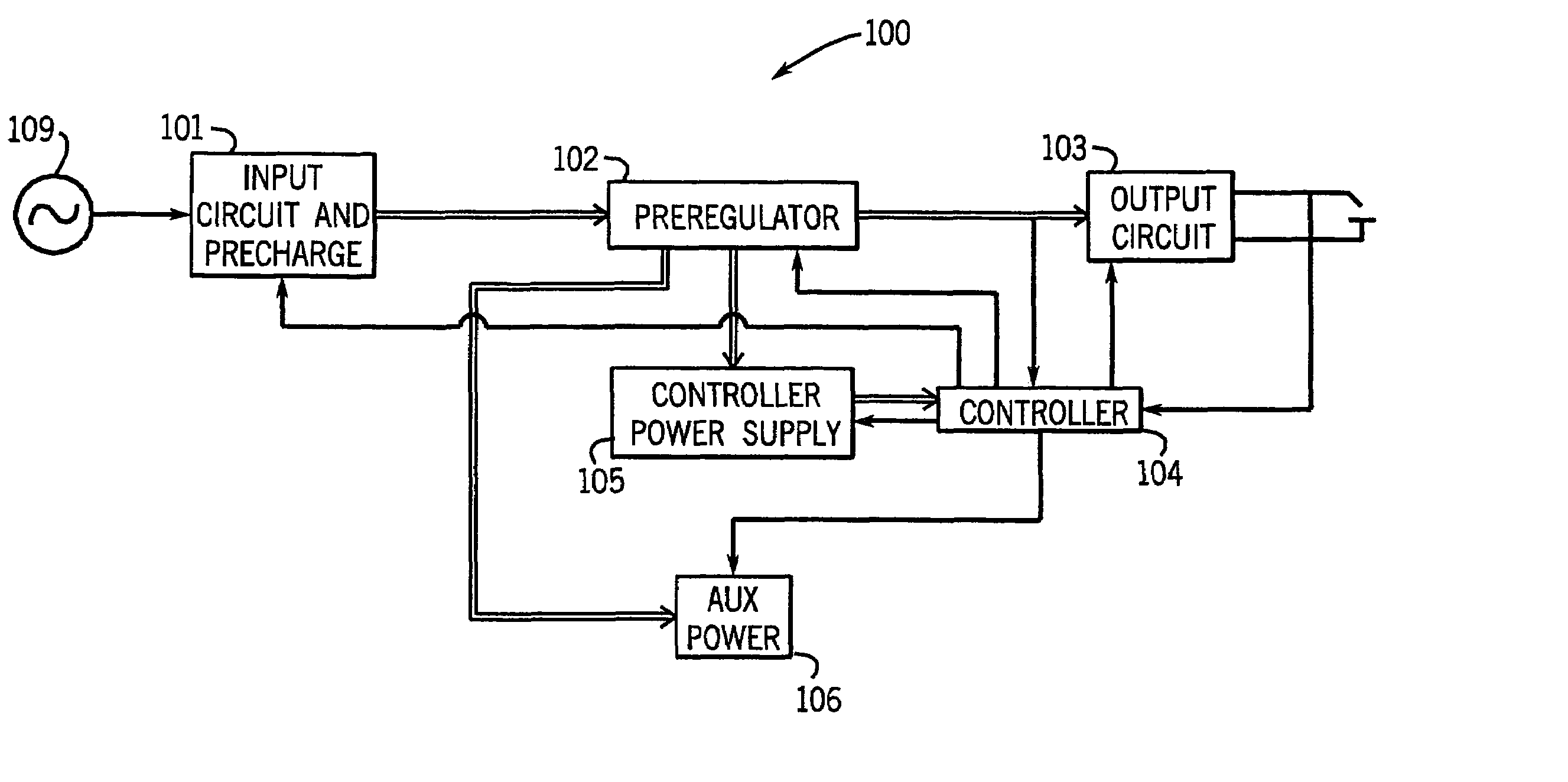
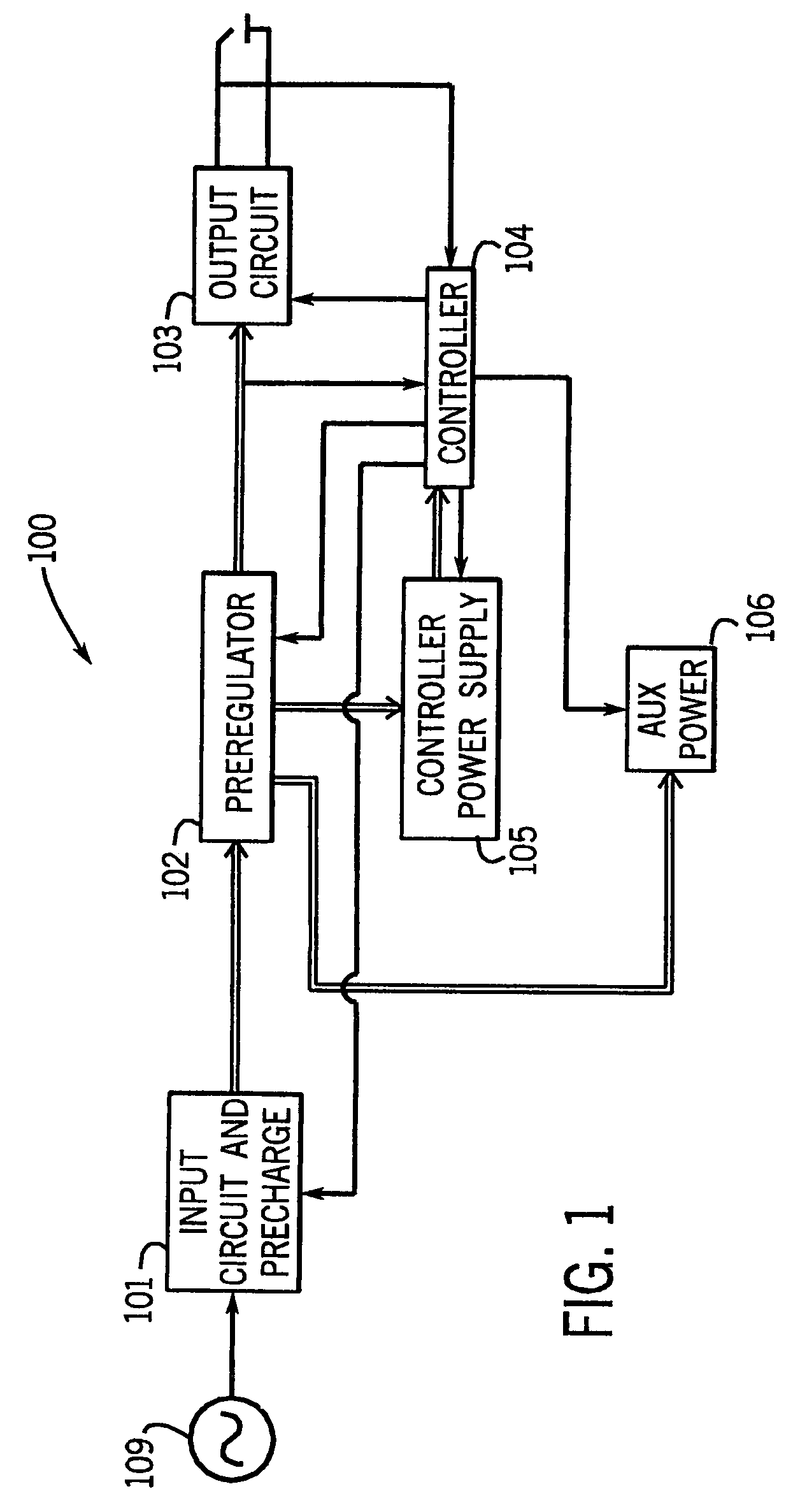
[0035]Referring now to FIG. 1, a welding power source 100 includes an input circuit 101, a preregulator 102, an output circuit 103, a controller 104, a controller power supply 105, and an aux power supply 106.

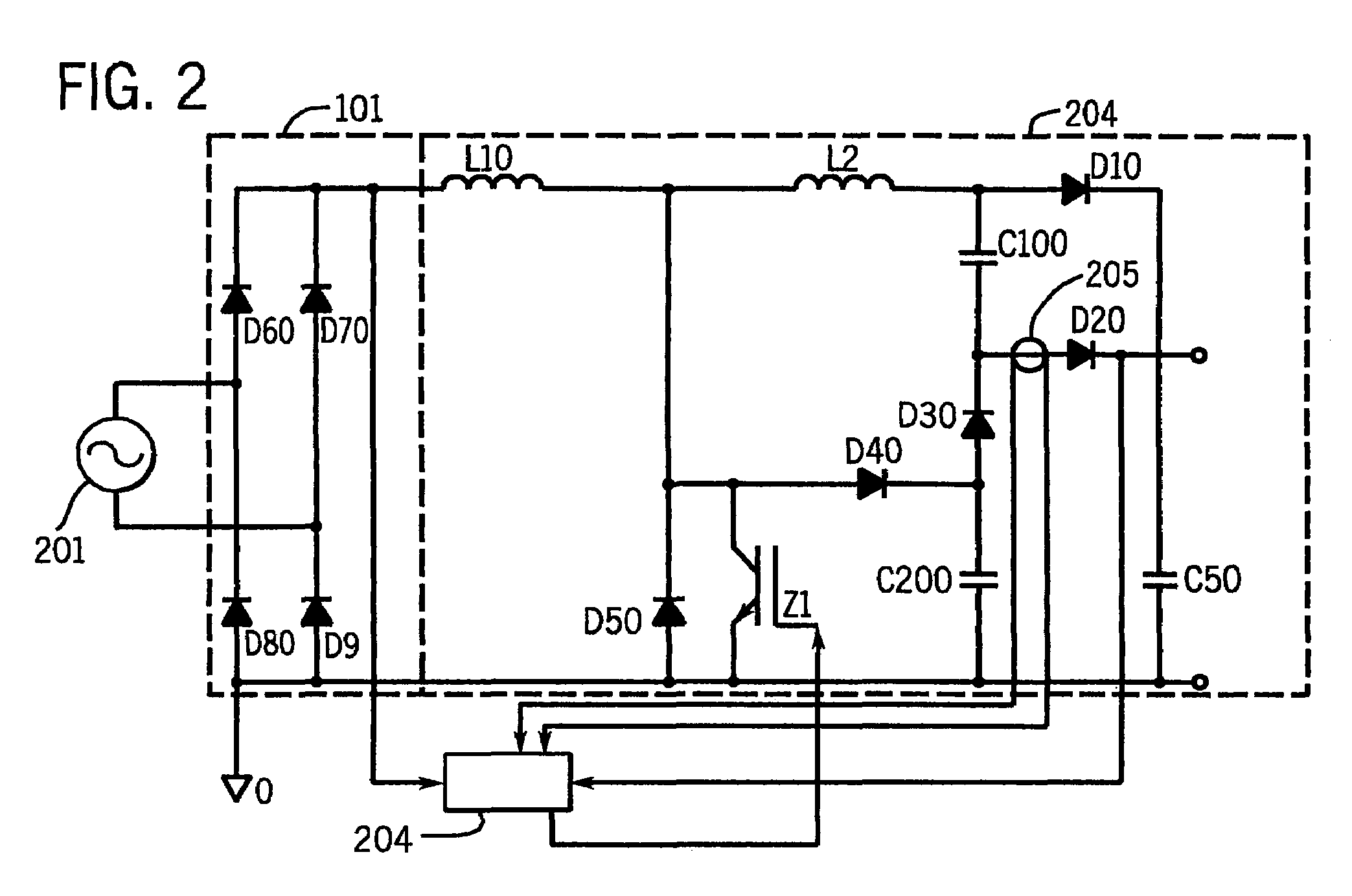
[0036]Input circuit 101 receives input utility or generator power, and provides a signal to preregulator 102. The input is ac, and the input circuit includes a rectifier and capacitor bank in the preferred embodiment. Thus, the output of the input circuit is a dc (uni-polar) signal, having a frequency twice that of the input frequency. Input circuit 101 is comprised of other components in alternative embodiments.

[0037]Preregulator 102 receives the signal from input ...


PUM

PropertyMeasurementUnit
Poweraaaaaaaaaa
Electric potential / voltageaaaaaaaaaa
Frequencyaaaaaaaaaa

Abstract

A method and apparatus for providing welding type power is disclosed. The power source is capable of receiving any input voltage over a wide range of input voltages and includes an input rectifier that rectifies the ac input into a dc signal. A dc voltage stage converts the dc signal to a desired dc voltage and an inverter inverts the dc signal into a second ac signal. An output transformer receives the second ac signal and provides a third ac signal that has a current magnitude suitable for welding, cutting or induction heating. The welding type current may be rectified and smoothed by an output inductor and an output rectifier. A controller provides control signals to the inverter and a controller power supply can also receive a range of input voltages and provide a control power signal to the controller, and a voltage independent of the input voltage.

Description

[0001]This is a continuation of, and claims the benefit of the filing date of, U.S. patent application Ser. No. 10 / 624,851, filed on Jul. 21, 2003, entitled “Method And Apparatus For Receiving A Universal Input Voltage In A Welding, Plasma Or Heating Power Source, which issued on Nov. 9. 2004 as U.S. Pat. No. 6,815,639, and is a continuation of U.S. patent application Ser. No. 09 / 969,535, filed Oct. 1, 2001, entitled Method And Apparatus For Receiving A Universal Input Voltage In A Welding, Plasma Or Heating Power Source, now abandoned, which is a continuation of U.S. patent application Ser. No. 09 / 540,567, filed Mar. 31, 2000, now Pat. No. 6,329,636, entitled Method And Apparatus For Receiving A Universal Input Voltage In A Welding, Plasma Or Heating Power Source.FIELD OF THE INVENTION[0002]This invention generally relates to power sources. More particularly, this invention relates to power sources employed in welding, cutting and heating applications.[0003]Power sources typically ...

Claims


Application Information

Patent Timeline
IPC IPC(8): B23K9/10B23K9/073B23K13/08H02M1/00H02M1/42H02M3/155H02M7/12H02M9/00
CPCB23K9/1006B23K9/1043B23K9/1056B23K13/08H02M1/4208B23K9/1062H02M2001/007H02M1/0006H02M1/007Y02P70/10
Inventor GEISSLER, STEVEN J.
Owner ILLINOIS TOOL WORKS INC
Why Eureka
Try Eureka