Magnetic circuit with coil

Inactive Publication Date: 2006-01-17
LEM INT SA
View PDF19 Cites 3 Cited by
  • Summary
  • Abstract
  • Description
  • Claims
  • Application Information

AI Technical Summary

Benefits of technology

[0006]In view of the above disadvantages, the object of the present invention is to provide a magnetic circuit with co

Problems solved by technology

Attaining a specified precision is often in conflict with the need to reduce manufacturing costs and the size of components.
Firstly, it is very difficult to remove the coil from the cylin

Method used


Image

  • Magnetic circuit with coil
  • Magnetic circuit with coil
  • Magnetic circuit with coil

Examples


Embodiment Construction

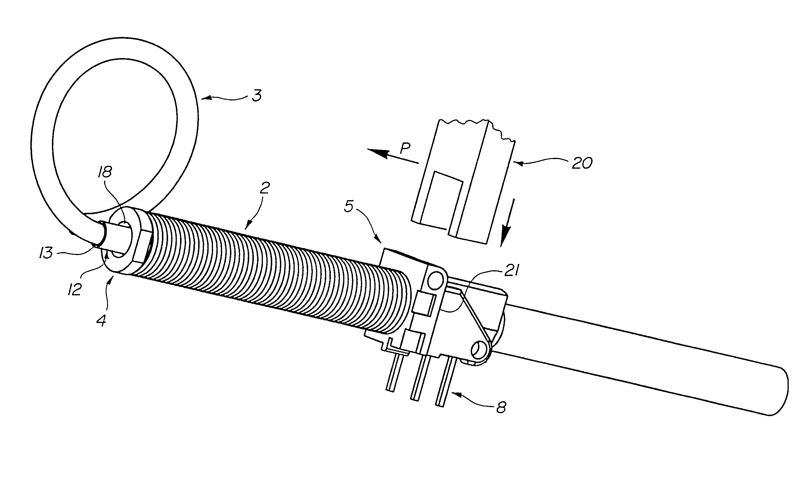
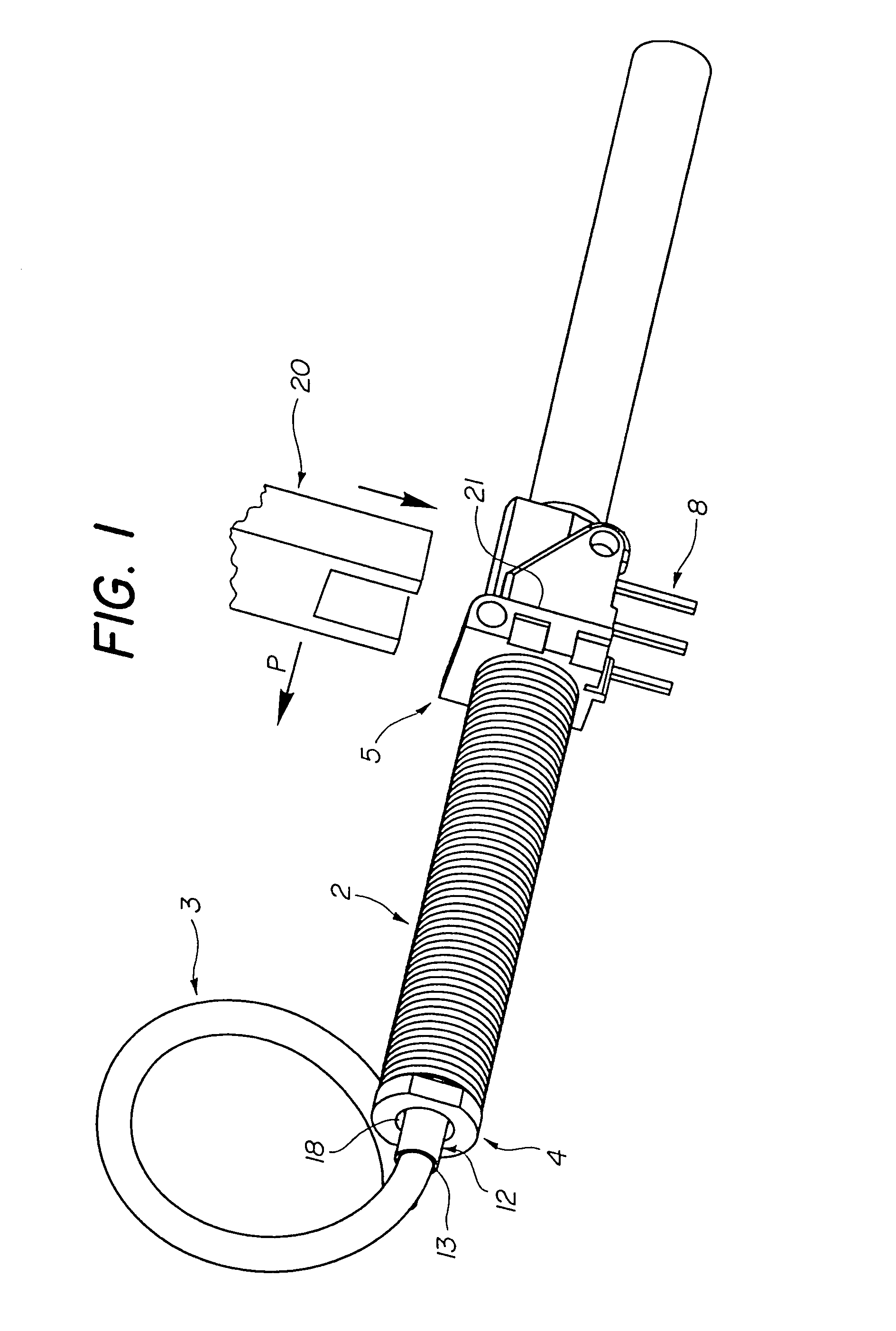
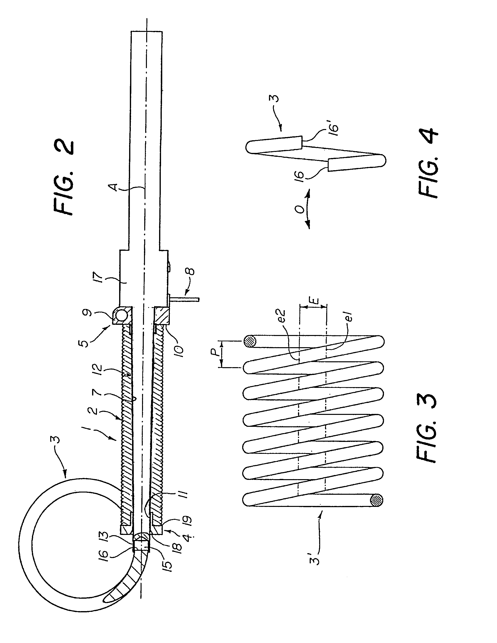
[0021]A magnetic circuit 1 with coil comprises a coil 2 and a magnetic core 3. The coil 2 comprises an end plate 4 at an insertion end 19, a connector 5 at the other end 10 and a conducting wire 6 wound around a central cavity 7 and extending between the connector 5 and the end plate 4. The conducting wire 6 may, for example, be made of conventional copper wire provided with an adhesive insulting layer to form the coil. The wire may also be a simple insulated wire, the adhesive being applied during formation of the coil.

[0022]The connector 5 comprises terminals 8 for connecting the magnetic circuit with coil to an electronic or other device. The terminals 8 are received in a housing 9 of the connector which also serves as a support for an end 10 of the coil and of the ends of conducting wires of the coil electrically connected to the terminals 8. Connection of the conducting wires to an external device is thus facilitated by integrating the connector 5 to the coil during manufacture...


PUM

PropertyMeasurementUnit
Angleaaaaaaaaaa
Shapeaaaaaaaaaa
Cell angleaaaaaaaaaa

Abstract

A magnetic circuit (1) with coil having an electric coil (2) and a magnetic core (3), the coil (2) comprising a conducting wire (6) and an end plate (4) and connector (5) being arranged at respective ends of the coil (2). The coil is mounted on the magnetic core (3) which is formed of a tore-shaped magnetic wire.

Description

[0001]This is a division of application Ser. No. 09 / 525,999, filed Mar. 15, 2000, now U.S. Pat. No. 6,640,419.BACKGROUND OF THE INVENTION[0002]The present invention relates to a magnetic circuit with a coil, and a method of making such a circuit.[0003]Magnetic circuits with coils are used in many fields including those relating to current sensors and transformers. In applications such as current sensors, measurement precision is closely related to the magnetic properties of the materials used and to the manufacturing precision. Attaining a specified precision is often in conflict with the need to reduce manufacturing costs and the size of components.[0004]A method of manufacturing a coil on a tore-shaped magnetic circuit is described in European patent EP 668 596. The method described in this patent, which attempts to respond to the above mentioned criteria, comprises the steps of winding a conducting wire coated with a thermo-adhesive around a cylindrical mandrel to form a coil, op...

Claims


Application Information

Patent Timeline
IPC IPC(8): H01F27/28H01F41/06H01F3/00H01F5/02H01F17/06H01F41/02H01F41/08
CPCH01F17/062H01F41/0206H01F41/08H01F5/02Y10T29/53257Y10T29/532Y10T29/49071Y10T29/49073Y10T29/4902
Inventor CATTANEO, FREDERIC
Owner LEM INT SA
Why Eureka
Try Eureka