

Built-in antenna for radio communication terminal
a radio communication terminal and built-in antenna technology, applied in the direction of antennas, antenna feed intermediates, antenna details, etc., can solve the problems of reducing the gain, the influence of the human body, and operating tabular reverse f-figured antennas b>2/b> also involves problems similar to those, and achieves the effect of less influence on the human body
- Summary
- Abstract
- Description
- Claims
- Application Information
AI Technical Summary
Benefits of technology
Problems solved by technology
Method used
Image

Examples
embodiment 1
(Embodiment 1)
[0120]FIG. 6 is a schematic view showing a configuration of a built-in antenna for a radio communication terminal according to Embodiment 1 of the present invention. The components shown in FIG. 6 are mounted in the package of the radio communication terminal, but an overall view of the radio communication terminal will be omitted for simplicity of explanation.
[0121]The built-in antenna for a radio communication terminal according to this embodiment is constructed of base plate 11, dipole antenna 12, balance-to-unbalance transformation circuit 13 and power supply terminals 14. The components will be explained below.
[0122]Base plate 11 is a tabular grounded conductor and attached in parallel to the plane (vertical plane) provided with operation buttons, a display and a speaker, etc. (not shown) in the radio communication terminal.
[0123]Dipole antenna 12 is constructed of two rectangular-wave-shaped (comb-shaped) antenna elements. This reduces the size of the dipole ante...
embodiment 2
(Embodiment 2)
[0131]Embodiment 2 is a mode in which the method of mounting dipole antenna 12 in Embodiment 1 is changed. Since Embodiment 2 is the same as Embodiment 1 except the method of mounting the dipole antenna, detailed explanations thereof will be omitted. Hereafter, differences from Embodiment 1 of the built-in antenna for a radio communication terminal according to this embodiment will be explained using FIG. 8. Components similar to those in Embodiment 1 are assigned the same reference numerals and detailed explanations thereof will be omitted.
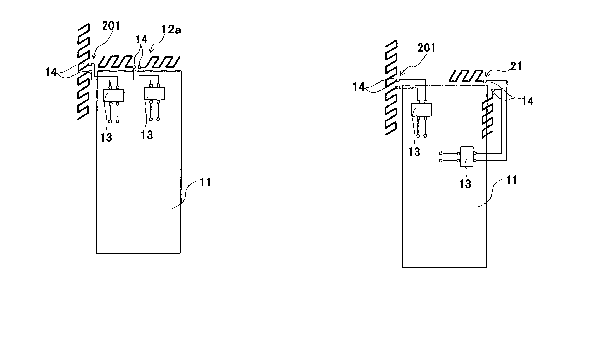
[0132]FIG. 8 is a schematic view showing a configuration of the built-in antenna for a radio communication terminal according to Embodiment 2 of the present invention. As shown in this figure, the built-in antenna for a radio communication terminal according to Embodiment 2 is constructed of base plate 11, dipole antenna 12a, balance-to-unbalance transformation circuit 13 and power supply terminals 14.
[0133]Dipole antenna 12a is att...
embodiment 3
(Embodiment 3)
[0136]Embodiment 3 is a mode in which the configuration and method of mounting of dipole antenna 12 in Embodiment 1 is changed. Since Embodiment 3 is the same as Embodiment 1 except for the configuration and method of mounting of the dipole antenna, detailed explanations thereof will be omitted. Differences of the built-in antenna for a radio communication terminal according to this embodiment from Embodiment 1 will be explained below using FIG. 9. The parts similar to those in Embodiment 1 are assigned the same reference numerals and detailed explanations thereof will be omitted.
[0137]FIG. 9 is a schematic diagram showing a configuration of the built-in antenna for a radio communication terminal according to Embodiment 3 of the present invention. As shown in this figure, the built-in antenna for a radio communication terminal according to Embodiment 3 is constructed of base plate 11, dipole antenna 21, balance-to-unbalance transformation circuit 13 and power supply te...
PUM
 Abstract
Description
Claims
Application Information