Thin film magnetic head including coil wound in toroidal shape and method for manufacturing the same
a technology of toroidal shape and magnetic head, which is applied in the direction of heads with metal sheet cores, instruments, record information storage, etc., can solve the problems of high risk of damage to the lower coil layer, inability to appropriately perform plating growth, and difficulty in forming through holes connected to each lower coil layer
- Summary
- Abstract
- Description
- Claims
- Application Information
AI Technical Summary
Benefits of technology
Problems solved by technology
Method used
Image
Examples
first embodiment
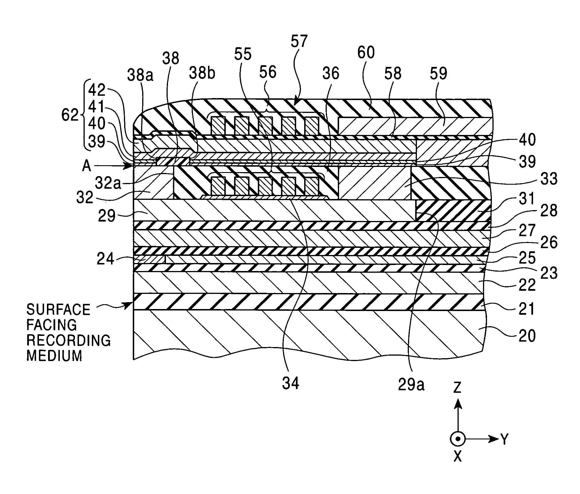
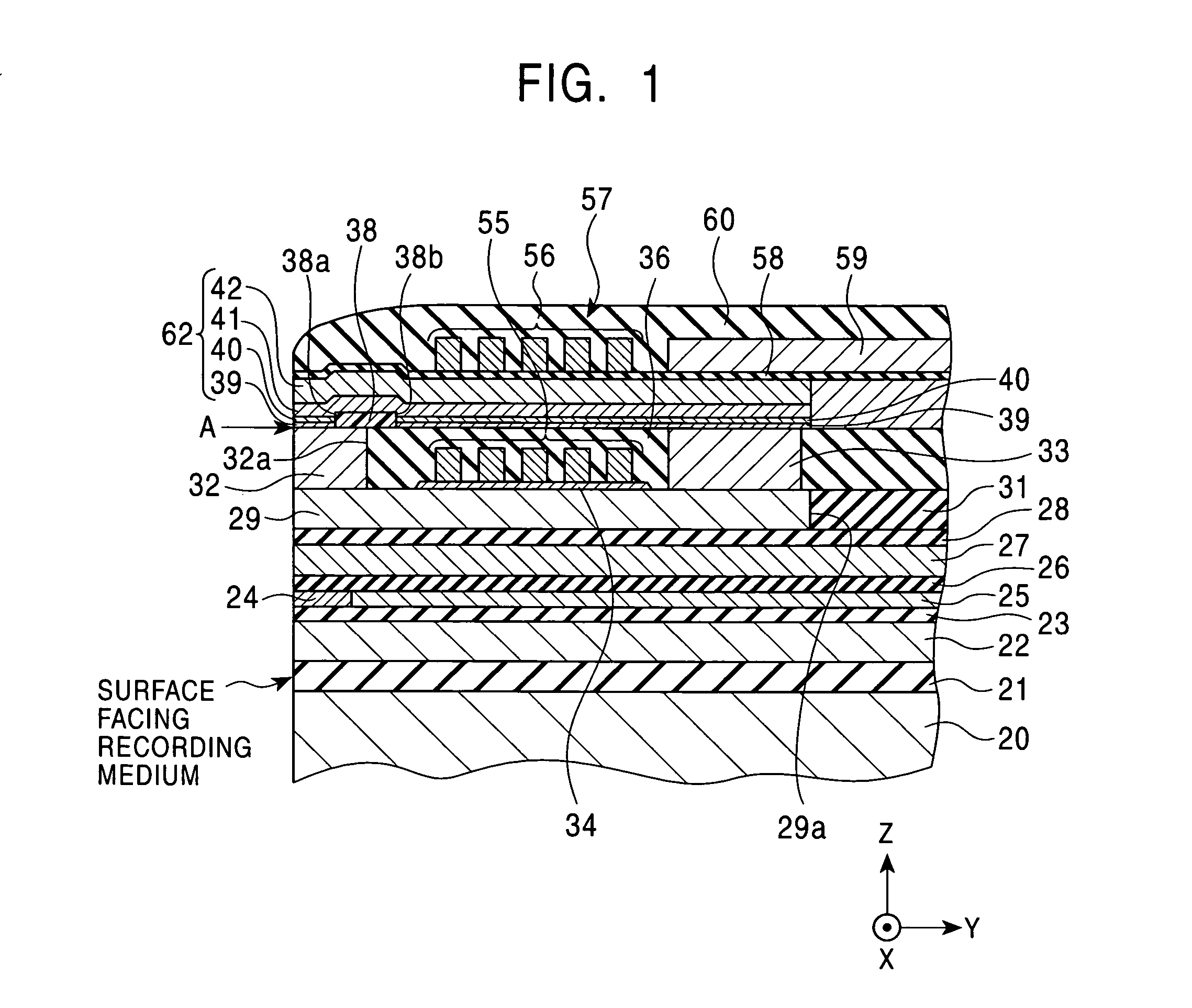
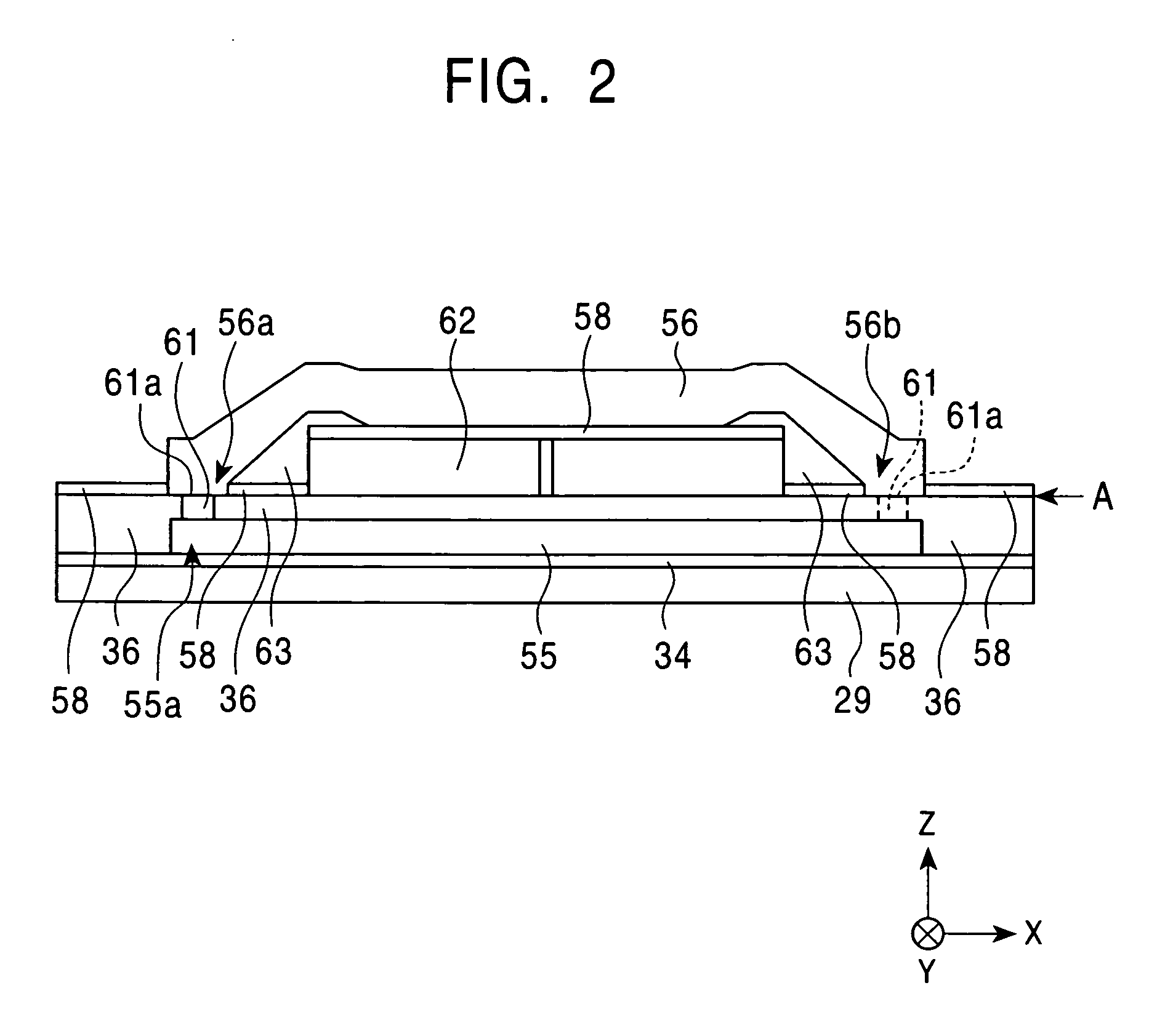
[0072]FIG. 1 is a partial vertical sectional view showing the structure of a thin film magnetic head according to the present invention. FIG. 2 is a partial front view of the thin film magnetic head shown in FIG. 1 wherein a protuberance layer 32, a protective layer 60, an MR head, and the like are not shown in the diagram, and a first coil piece, a second coil piece, and the like provided at the locations closest to a surface facing a recording medium are viewed from the side of the surface facing the recording medium. FIG. 3 is a partial plan view showing a coil structure of the thin film magnetic head shown in FIG. 1. FIG. 4 is a partial perspective view of a magnified part of the structure of the thin film magnetic head shown in FIG. 1.
[0073]Hereafter the X direction shown in the drawing is referred to as the track-width direction, and the Y direction shown in the drawing is referred to as the height direction. The Z direction shown in the drawing is the direction of movement of...
fifth embodiment
[0158]FIG. 20 is a partial vertical sectional view showing the structure of a thin film magnetic head according to the present invention. The thin film magnetic head shown in FIG. 20 has substantially the same structure as that of the thin film magnetic head shown in FIG. 1. Therefore, constituents of the thin film magnetic head shown in FIG. 20 similar to those of the thin film magnetic head shown in FIG. 1 are indicated by the same reference numerals as in FIG. 1, and detailed explanations thereof will not be provided.
[0159]In the thin film magnetic head shown in FIG. 20, the top surfaces of first coil pieces 455 are flush with a reference surface A, and the top surface of a protuberance layer 32, the top surfaces of the first coil pieces 455, the top surface of a coil insulating layer 36, and the top surface of a back gap layer 33 are a continuous flattened surface along the above-described reference surface A.
[0160]A Gd-determining layer 438 is provided from the location at a pr...
sixth embodiment
[0190]FIG. 27 is a partial vertical sectional view showing the structure of a thin film magnetic head according to the present invention. FIG. 28 is a partial front view of the thin film magnetic head shown in FIG. 27 wherein an MR head, an insulating layer 536, a protective layer 564, and the like are not shown in the drawing, and a structure composed of a magnetic pole end layer, a first coil piece and a second coil piece provided at the locations closest to a surface facing a recording medium, and each layer facing these layers in the film thickness direction is viewed from the side of the surface facing the recording medium.
[0191]A playback head (may be referred to as an MR head) from the above-described lower shield layer 22 to the above-described upper shield layer 27 is the same as that in the thin film magnetic head according to any one of the first embodiment to the fifth embodiment.
[0192]As shown in FIG. 27, a separation layer 28 formed from Al2O3 or the like is provided o...
PUM
 Abstract
Description
Claims
Application Information
 - R&D
- Intellectual Property
- Life Sciences
- Materials
- Tech Scout
- Unparalleled Data Quality
- Higher Quality Content
- 60% Fewer Hallucinations
Browse by: Latest US Patents, China's latest patents, Technical Efficacy Thesaurus, Application Domain, Technology Topic, Popular Technical Reports.
© 2025 PatSnap. All rights reserved.Legal|Privacy policy|Modern Slavery Act Transparency Statement|Sitemap|About US| Contact US: help@patsnap.com


