Disk storage system with removable arrays of disk drives
a disk drive and storage system technology, applied in the direction of record information storage, instruments, cabinet/cabinet/drawer, etc., can solve the problems of system not efficiently using rack space, high probability of being catastrophic, and the failure of the disk drive, so as to reduce the number of single points, the effect of high degree of symmetry and overlap
- Summary
- Abstract
- Description
- Claims
- Application Information
AI Technical Summary
Benefits of technology
Problems solved by technology
Method used
Image
Examples
embodiment 100
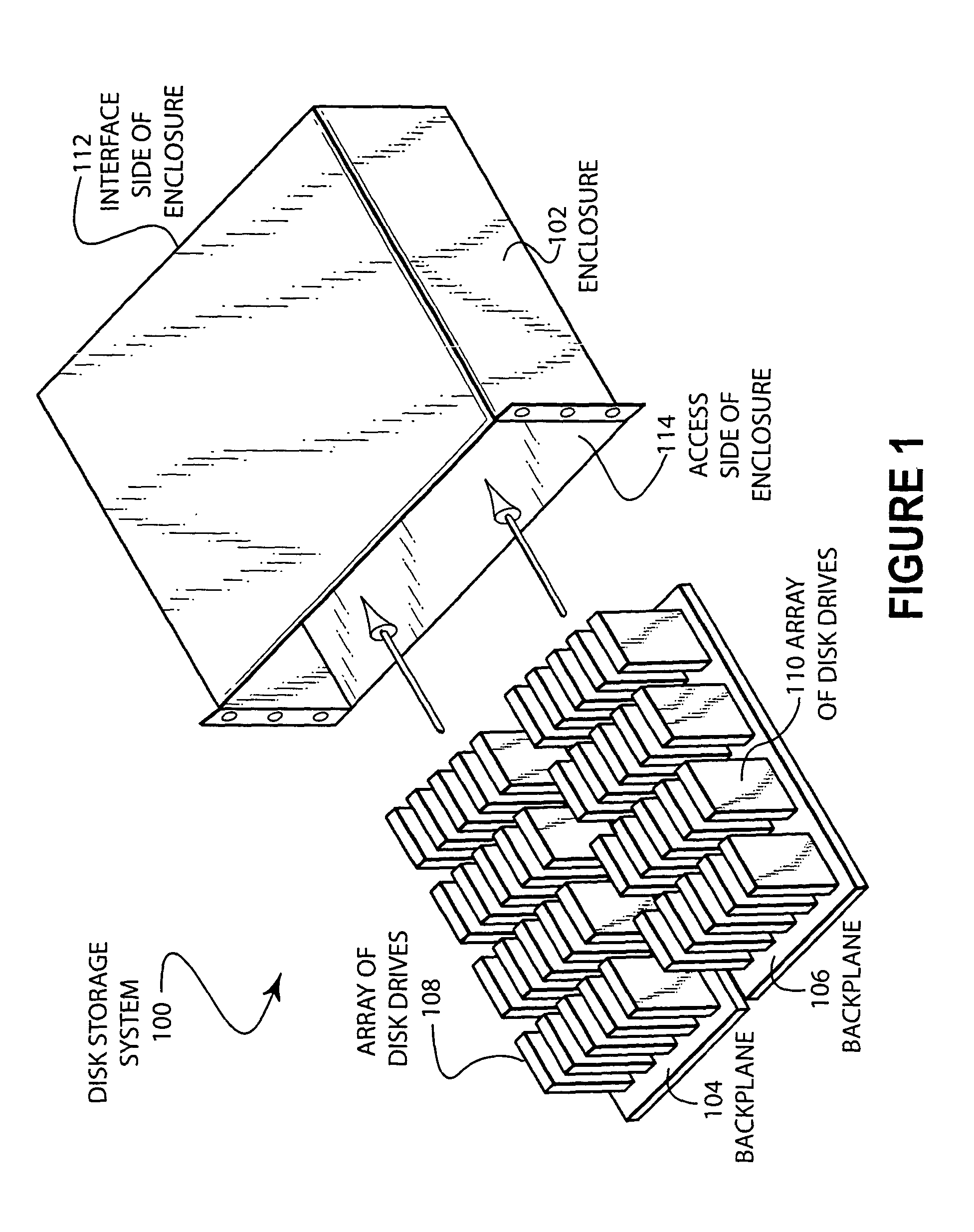
[0020]FIG. 1 illustrates an embodiment 100 of the present invention showing a disk storage system. An enclosure 102 may contain removable backplanes 104 and 106. Backplane 104 has an array 108 of disk drives while backplane 106 has an array 110 of disk drives. The enclosure 102 has an interface side 112 and an access side 114.
[0021]The embodiment 100 has two removable backplanes 104 and 106 on which are mounted an array of disk drives. By mounting the disk drives to a removable backplane, several rows of disk drives may be placed into the enclosure 102 while allowing periodic service to occur.
[0022]The two separate arrays of disks 108 and 110 may be controlled by a RAID controller or other controller. In some cases, an interface within the enclosure 102 may serve to route connections from the interface side 112 of the enclosure to the individual disk drives. In other cases, intelligent control may be used within the enclosure to manage the multitude of disk drives. Such intelligent ...
embodiment 200
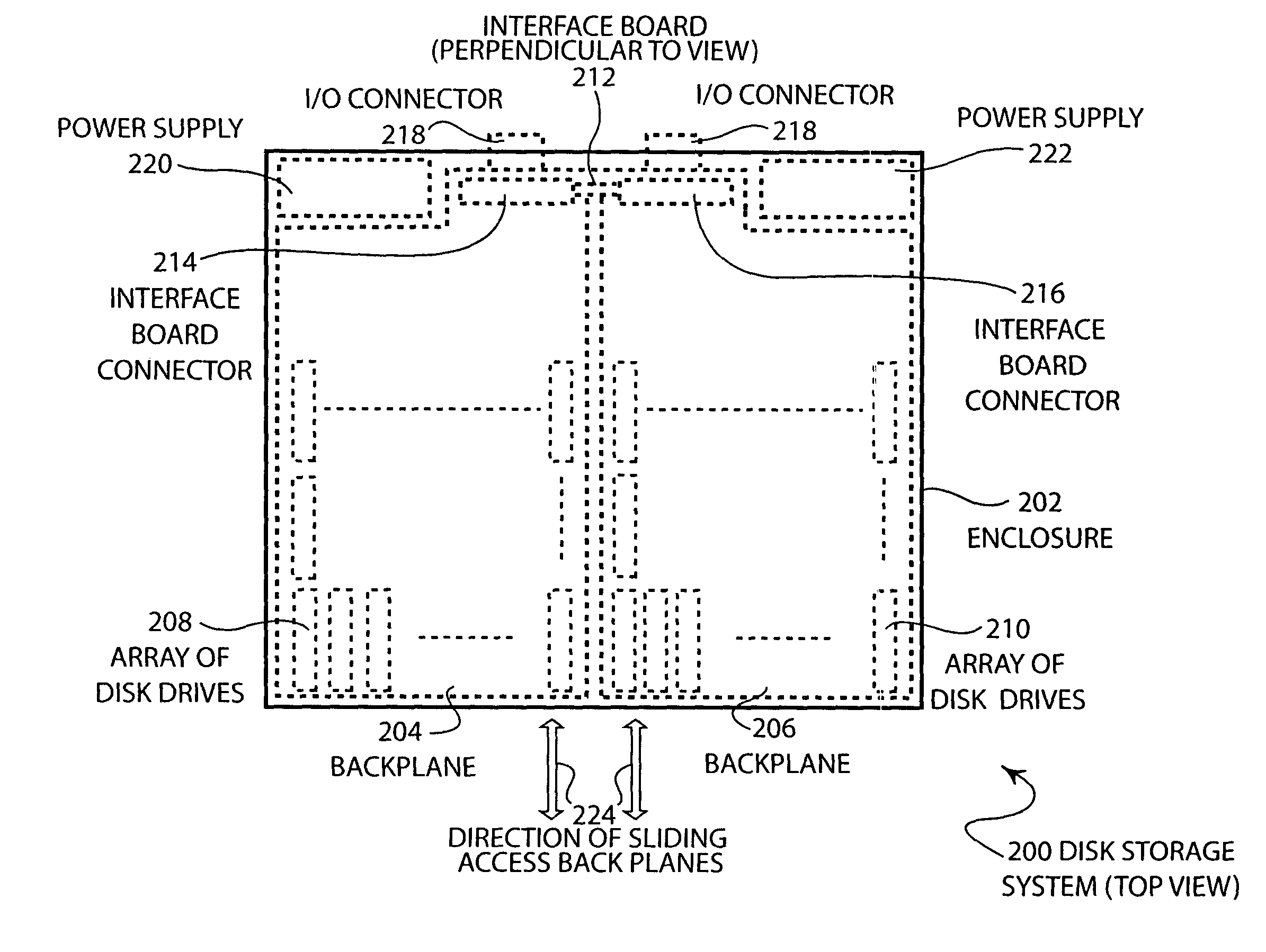
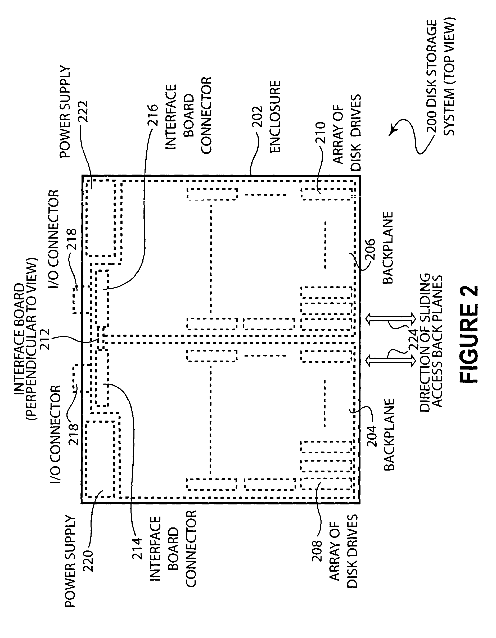
[0025]FIG. 2 illustrates a top view of an embodiment 200 of the present invention showing a disk storage system. An enclosure 202 contains backplanes 204 and 206. Backplane 204 has an array of disk drives 208 as backplane 206 has an array of disk drives 210. An interface board 212 has an interface board connector 214 that electrically connects to the backplane 204. Likewise, interface board connector 216 electrically connects to the backplane 206. The interface board 212 has I / O connectors 218 that allow communication to other devices. Power supplies 220 and 222 are also mounted in the enclosure 202. The backplanes 204 and 206 may be installed and removed from the enclosure 202 in the direction depicted by arrows 224.
[0026]The interface board 212 is illustrated as perpendicular to the plane of the view. In some embodiments, such an orientation may afford the designer a convenient method for connecting the various cables, connectors, and printed circuit boards that make up an embodim...
embodiment 300
[0035]FIG. 3 illustrates an embodiment 300 of the present invention showing the interconnections of various components within a disk storage system. The enclosure 302 contains an interface / controller board 304 that connects to other devices through input / output signals 306. The interface / controller board 304 engages backplanes 308 and 310. Backplane 308 connects to a plurality of disk drives 312. Backplane 310 connects to a plurality of disk drives 314. The interface / controller board 304 may also interface to power supplies 316 and 318. The backplane 308 and the disk drives 312 make up a removable unit 320. The backplane 310 and the disk drives 314 make up a removable unit 322.
[0036]The electrical and communication connections between the various components may be through cables, direct plug in of mating connectors, or by any other electrical connection mechanism whether or not such mechanism is removable, with the exception of the connections between the backplanes and the interfac...
PUM
| Property | Measurement | Unit |
|---|---|---|
| mechanical | aaaaa | aaaaa |
| depth | aaaaa | aaaaa |
| degree of symmetry | aaaaa | aaaaa |
Abstract
Description
Claims
Application Information
 - R&D
- Intellectual Property
- Life Sciences
- Materials
- Tech Scout
- Unparalleled Data Quality
- Higher Quality Content
- 60% Fewer Hallucinations
Browse by: Latest US Patents, China's latest patents, Technical Efficacy Thesaurus, Application Domain, Technology Topic, Popular Technical Reports.
© 2025 PatSnap. All rights reserved.Legal|Privacy policy|Modern Slavery Act Transparency Statement|Sitemap|About US| Contact US: help@patsnap.com


