Process for recovering digital optical signals and a feedback decision circuit

a decision circuit and digital optical technology, applied in pulse technique, dc level restoring means or bias distortion correction, baseband system details, etc., can solve the problem that the dfe known from fig. 1 is not capable of processing data rates above 10 gbit/s, and achieves the effect of facilitating the assessment and adjustment of the thresholds of decision elements, facilitating analogue control of determining parameters, and simple and rapid adaptation of controlled variables

Inactive Publication Date: 2006-01-17
ALCATEL LUCENT SAS
View PDF9 Cites 38 Cited by
  • Summary
  • Abstract
  • Description
  • Claims
  • Application Information

AI Technical Summary

Benefits of technology

[0006]The process according to the invention for recovering severely disturbed, digital optical signals has the advantage that the speed of a parallel connection of threshold decision elements in a DFE is combined with the simple and rapid adaptation of controlled variables by an analogue control circuit. It is also advantageous to integrate a pseudo-error monitor which facilitates the assessment and adjustment of the decision element thresholds in the equalizer based on the quality of the signal. The feedback equalizer according to the invention also has the advantage that a synthetic, dispersive signal is generated, which facilitates an analogue control for determining the parameters. The integration of the pseudo-error monitor improves the equalizer, so that the decision thresholds can be adjusted based on the analysis of the pseudo-error and can be adapted to the prevailing circumstances of the transmission link.

Problems solved by technology

However, on the basis of currently available semiconductor circuits, the DFE known from FIG. 1 is not capable of processing data rates above 10 GBit / s.
However, in this decision circuit no difference signal between disturbed input signal 1 and fed-back signal is available for generating the error signal 10.

Method used


Image

  • Process for recovering digital optical signals and a feedback decision circuit
  • Process for recovering digital optical signals and a feedback decision circuit
  • Process for recovering digital optical signals and a feedback decision circuit

Examples


Embodiment Construction

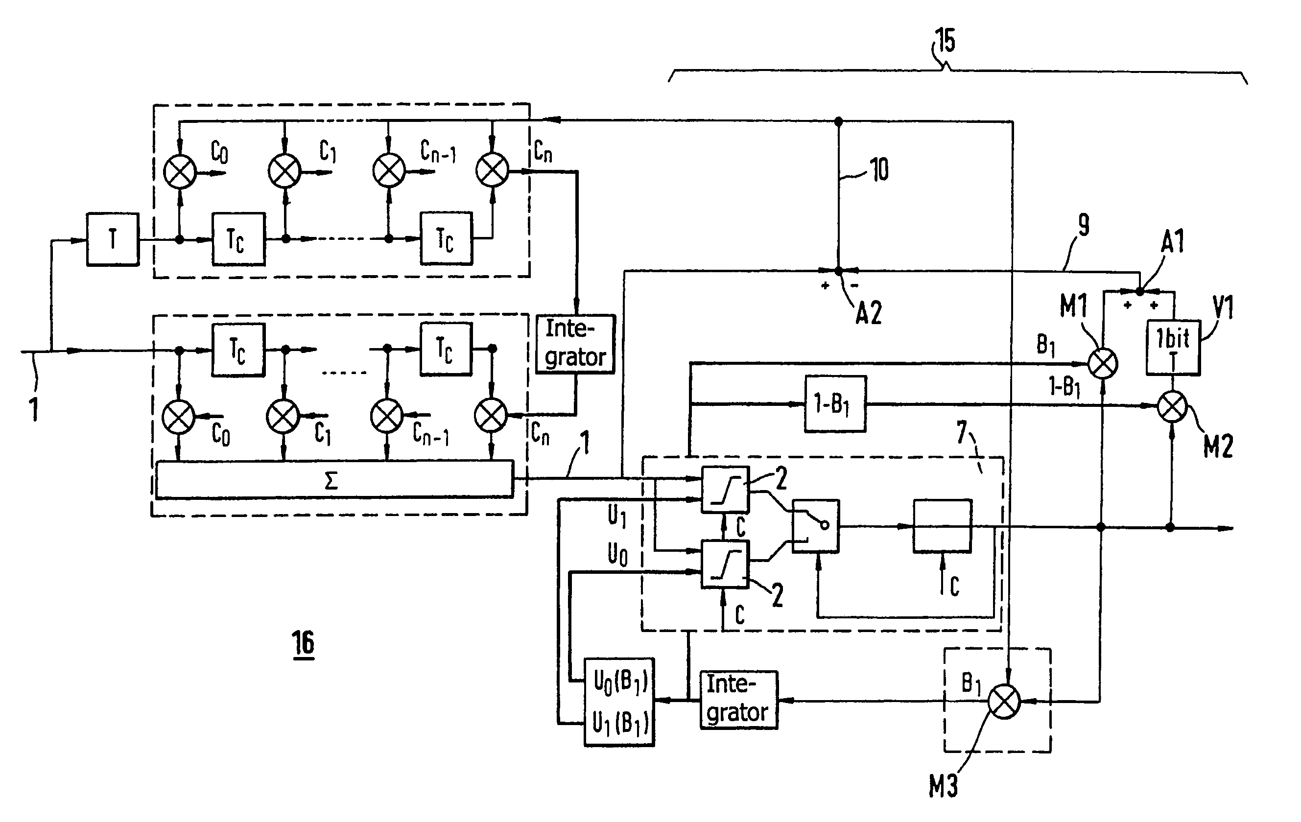
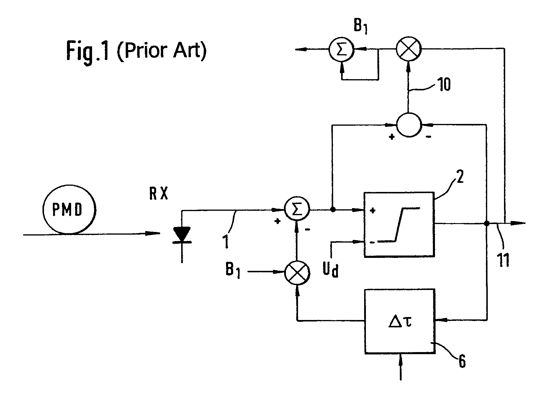
[0014]FIG. 3 shows the main components of the equalizer according to the invention. A disturbed optical signal 1 is applied to a DFE 7. In this exemplary embodiment a DFE with two threshold decision elements, requiring two setting parameters, is used. The output of the DFE 7 supplies a signal 11 in respect of which a decision has been made. An analogue control stage 15 is shown in a broken-line frame. This analogue control stage 15 supplies setting parameters B1 and 1-B1 at its input end to the DFE. To perform the analogue control—as described in the prior art and with reference to FIG. 1—an adder A2, a multiplier M3, an adder A3 and a multiplier M4 and an adder A4 are used in the circuit according to the invention. A synthetic dispersive signal 9 and the disturbed optical signal 1 serve as input signal for the adder A2. The synthetic dispersive signal 9 is generated by tapping the decided signal 11, at nodes 8, and the fed-back setting parameters B1 and 1-B1. The first parameter B1...


PUM


Abstract

A process is proposed for recovering disturbed digital signals, wherein the electrical signals pass through a feedback equalizer and an analogue control of the setting parameters of the equalizers is performed. A pseudo-error monitor, which facilitates a high-speed adjustment of decision element thresholds, is also provided.

Description

BACKGROUND OF THE INVENTION[0001]This invention relates a process for recovering disturbed, digital, optical signals and a feedback decision circuit used in such a process.[0002]The prior art has disclosed processes for recovering severely disturbed, digital, optical signals and feedback equalizers (DFE=Decision Feedback Equalizer). For example, the publication “Equalization of Bit Distortion Induced by Polarisation Mode Dispersion”, H. Bülow, NOC 97, Antwerp 1997, p. 65 to 72 presents several possibilities of compensating dispersion using equalizers. FIG. 1 illustrates an equalizer known from the prior art. A disturbed transmitted optical signal is converted into a disturbed electrical signal 1 in an opto-electric converter. The disturbed signal is applied to a threshold decision element 2. From the output of the threshold decision element 2, the decided signal 11 is fed-back via a delay element 6. Via a multiplier the fed-back, time-delayed signal is multiplied by a parameter B1 a...

Claims


Application Information

Patent Timeline
Patent Type & Authority Patents(United States)
IPC IPC(8): H03H7/30H04B10/2507H04B3/06H04B10/07H04B10/25H04L25/03H04L25/06
CPCH04L25/03057H04L25/063H04L2025/0349
Inventor BUCHALI, FREDBULOW, HENNING
Owner ALCATEL LUCENT SAS
Why Eureka
Try Eureka