
Physical quantity detecting device having second lead conductors connected to the electrodes and extending to the circumference of the substrate

Inactive Publication Date: 2006-01-24
HITACHI LTD +1
View PDF12 Cites 21 Cited by
  • Summary
  • Abstract
  • Description
  • Claims
  • Application Information

AI Technical Summary

Benefits of technology

[0005]Accordingly, it is an object of the present invention to provide a simple-structure physical quantity detecting device whose resistance does not vary irrespective of use for long periods, a method for manufacturing thereof and a motor vehicle control system using the physical quantity detecting sensor to improve its reliability.
[0007]This arrangement can provide a simple structure without any variation in resistance irrespective of use for long periods.
[0009]This arrangement can provide a simple-structure physical quantity detecting device whose resistance does not vary irrespective of use for long periods.

Problems solved by technology

However, the type using a conductive film different from the heater resistor creases a problem on complication of the sensor structure.

Method used


Image

  • Physical quantity detecting device having second lead conductors connected to the electrodes and extending to the circumference of the substrate
  • Physical quantity detecting device having second lead conductors connected to the electrodes and extending to the circumference of the substrate
  • Physical quantity detecting device having second lead conductors connected to the electrodes and extending to the circumference of the substrate

Examples


seventh embodiment

Furthermore, referring to FIGS. 21 and 22, a description will be given hereinbelow of a construction of a thermal type airflow sensor serving as a physical quantity detecting device according to the present invention.

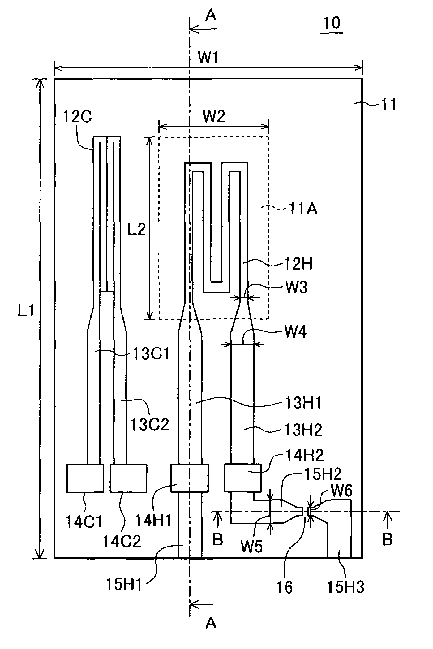
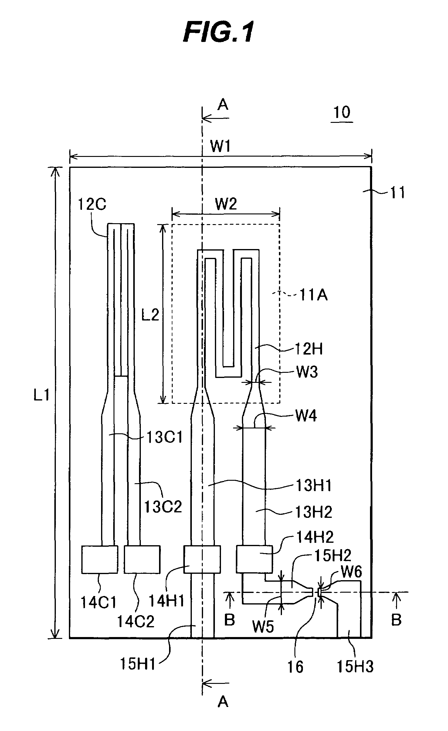
[0140]FIG. 21 is a plan view showing a thermal type airflow sensor serving as a physical quantity detecting device according to a seventh embodiment of the present invention, and FIG. 22 is a cross-sectional view taken along A—A of FIG. 21.

[0141]Although in the embodiments described with reference to FIGS. 1 to 20 a semiconductor substrate has been used as a substrate for the formation of the heat generating resistors, the substrate material is not limited to the semiconductor, but other substrates are usable. In this embodiment, a metal is employed as a substrate material.

[0142]As FIG. 21 shows, a plurality of thermal type airflow sensors 10S, 10T and 10U are simultaneously manufactured on a metal-made substrate 50. Each of the airflow sensors 10S, 10T and 10U has a co...


PUM


Abstract

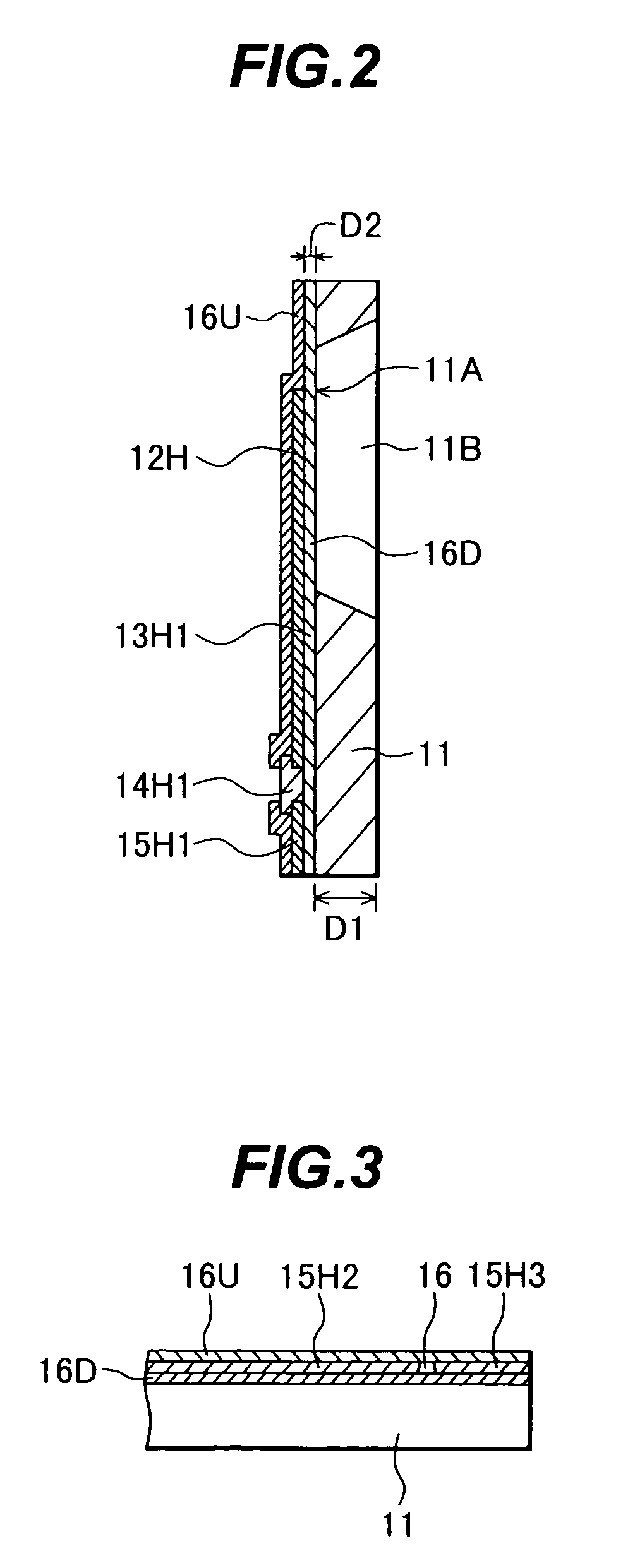
It is an object of the present invention to provide a simple-structure physical quantity detecting device whose resistance does not vary irrespective of use for long periods, a method for manufacturing thereof and a motor vehicle control system using the physical quantity detecting sensor to improve its reliability. An airflow sensor (20) is equipped with a heat generating resistor (12H) and a temperature measuring resistor (12C), formed on a semiconductor substrate (11). The heat generating resistor (12H) is formed in a thin-wall portion (11A). Both end portions of the heat generating resistor (12H) are connected through first lead conductors (13H1, 13H2) to electrodes (14H1, 14H2), respectively. A second lead conductor (15H1) connected to the electrode (14H1) extends to an outer circumferential portion of the airflow sensor (10). A second lead conductor (15H2, 15H3) connected to the electrode (14H2) also extend to the outer circumferential portion of the airflow sensor (10), but a disconnection portion (16) is made in the middle thereof to establish electrical non-conduction.

Description

TECHNICAL FIELD[0001]The present invention relates to a physical quantity detecting device for detecting physical quantities such as flow rate, pressure, temperature, humidity, acceleration and gas concentration, a method for manufacturing a physical quantity detecting device and a motor vehicle control system using the physical quantity detecting device, and more particularly to a physical quantity detecting device, a method for manufacturing a physical quantity detecting device and a motor vehicle control system using the physical quantity detecting device, suitable for use of a small-sized sensor.BACKGROUND ART[0002]So far, as an airflow sensor placed in an intake air passage of an internal combustion engine or the like for measurement of air quantity, the principal tendency has been toward a thermal type for direct detection of mass air quantity. Recently, particular attention has been focused on a small-sized airflow sensor produced through the use of the semiconductor micromac...

Claims


Application Information

Patent Timeline
IPC IPC(8): G01F1/68F02D41/18G01F1/684G01F1/692G01P15/12H01C17/02
CPCF02D41/187G01P15/123G01F1/6845G01F1/692F02D41/1454F02D41/182F02D2200/703F02D2200/0414G01P2015/0828H01L2224/48091H01L2224/73265H01L2924/00014H01C17/02
Inventor WATANABE, IZUMINAKADA, KEIICHIYAMADA, MASAMICHI
Owner HITACHI LTD
Learn More