Method and apparatus for mounting a heat transfer apparatus upon an electronic component

a technology for heat transfer apparatuses and electronic components, applied in lighting and heating apparatuses, cooling/ventilation/heating modifications, semiconductor devices, etc., can solve problems such as graphite cracking and fracture, reliability, life expectancy, and graphite degradation, so as to achieve uniform and efficient heat transfer and simple and cost-effective methods

Inactive Publication Date: 2006-01-24
INT BUSINESS MASCH CORP
View PDF12 Cites 11 Cited by
  • Summary
  • Abstract
  • Description
  • Claims
  • Application Information

AI Technical Summary

Benefits of technology

[0014]It is another aspect of the present invention to provide for a simple and cost effective approach for transferring heat from an electronic component using a graphite-based heat transfer apparatus. This is done in a manner, which substantially reduces a tendency of the graphite material to mechanically and thermally degrade.
[0015]It is yet another aspect of the present invention to provide for a compliant actuating mechanism for allowing adjustment of actuating forces applied by the apparatus to thereby adjust the forces being applied at the heat transfer interface, whereby a more uniform and efficient transfer of heat occurs.
[0016]It is still another aspect of the present invention to use graphite heat sinks that can be mechanically loaded on an electronic component without inducing failure in the graphite as by crack generation and propagation or even inducing discontinuities in the adhesive layers at the thermal interfaces.

Problems solved by technology

Excessive heat, however, degrades their performance, reliability, life expectancy, and even causes failure.
Despite such advantages, however, limitations on its use nevertheless exist.
These are due primarily to the tendency of graphite to crack and fracture when subjected to heavy loading.
Such cracking can cause corresponding cracking in the thermal paste at the thermal interface, thereby lessening thermal conductivity.
Therefore, without the ability for effectively transferring heat from an electronic component, especially in an MCM environment, by using graphite-based heat sinks in a manner that avoids mechanical and thermal degradations, the true potential of using such heat sinks is not entirely realized.

Method used


Image

  • Method and apparatus for mounting a heat transfer apparatus upon an electronic component
  • Method and apparatus for mounting a heat transfer apparatus upon an electronic component
  • Method and apparatus for mounting a heat transfer apparatus upon an electronic component

Examples


Embodiment Construction

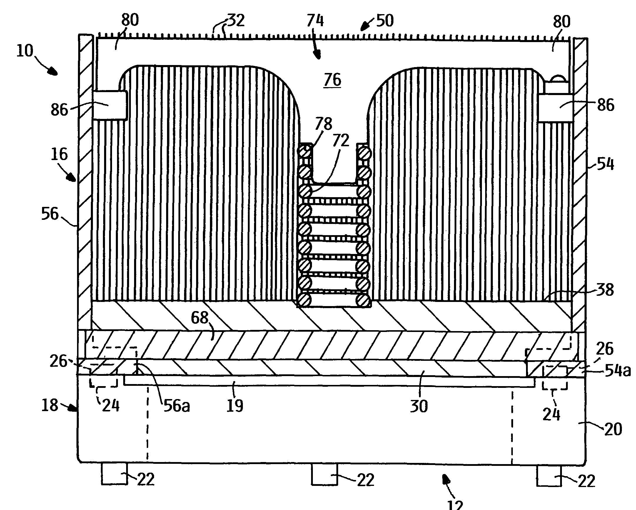
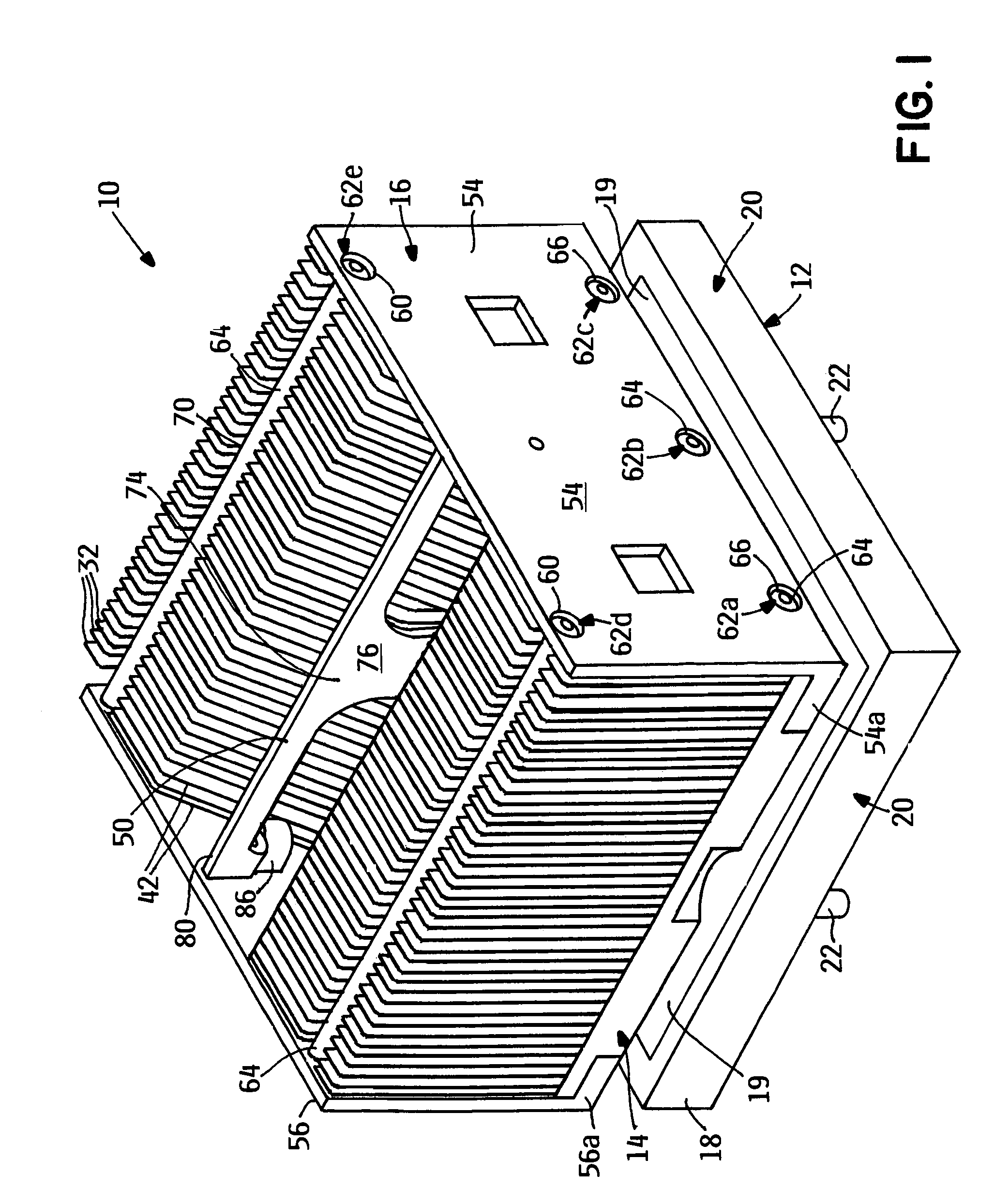
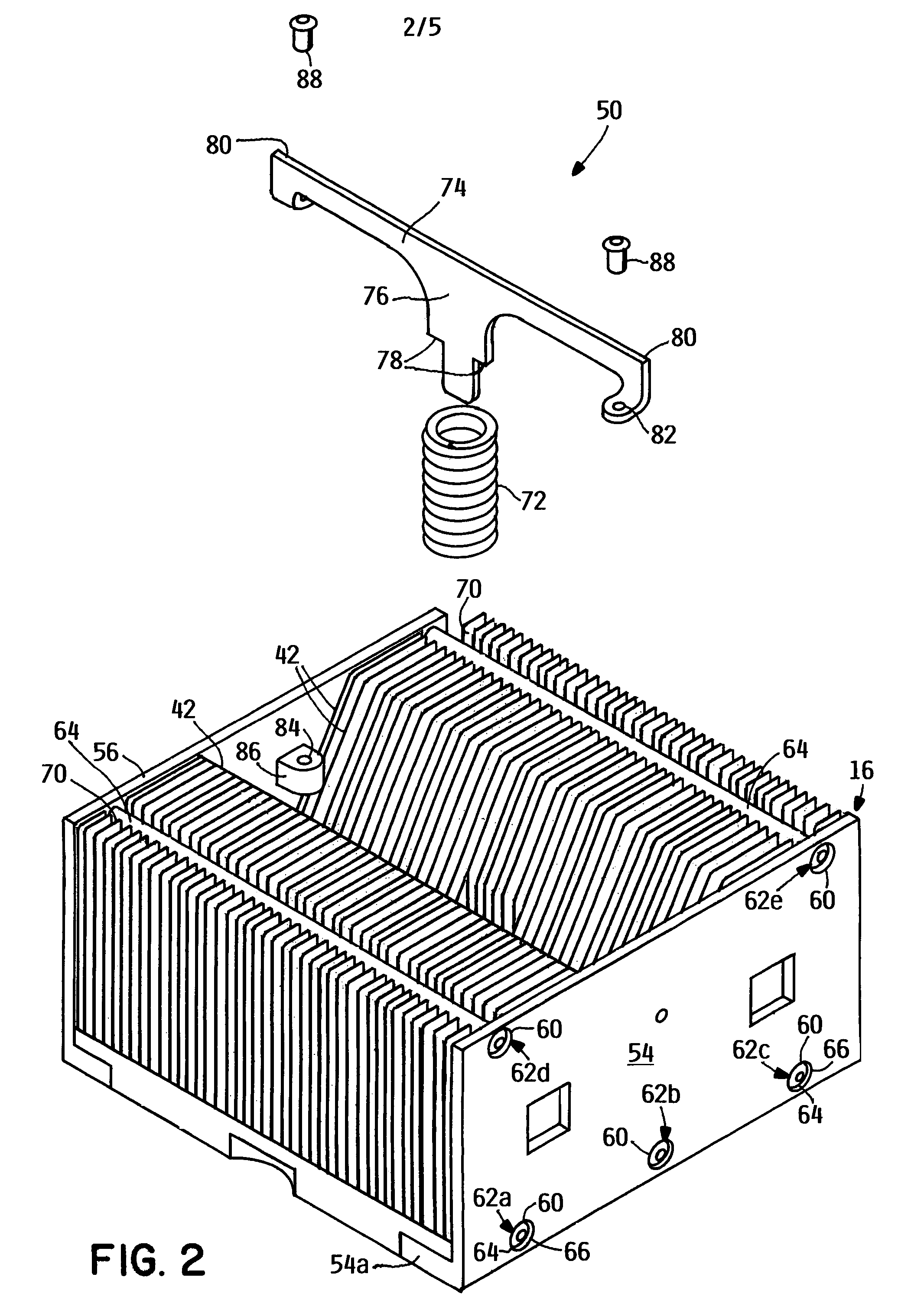
[0023]Reference is now made to FIGS. 1–5 for illustrating one preferred embodiment of a heat transfer apparatus 10 made according to the present invention, which implements an improved process of mounting the same on a heat source, such as an electronic component 12. In this embodiment, the electronic component 12 is a multi-chip module (MCM) 12.

[0024]The heat transfer apparatus 10 essentially includes a thermal conducting element 14 and a mounting assembly 16 for removable mounting upon the MCM 12. The MCM 12 includes a MCM housing assembly 18 that houses a multi-chip module substrate 19 (FIGS. 1 & 3) which when operable generates the heat that is to be transferred by this embodiment. The MCM housing assembly 18 includes an annular cap 20 that has a configuration, which generally matches the periphery of the MCM 12. The annular cap 20 is a thermally conductive material, such as copper and provides many features that are not described herein since they do not, per se, form an aspect...


PUM


Abstract

A heat transfer apparatus comprises a thermally conductive member including a base having one or more surfaces adapted to absorb heat from an electronic component, and a mounting assembly including at least one mounting member directly coupled to the base and for direct attachment to the electronic component so that loading forces for mounting on it the electronic component are not directly applied to the base. The thermally conductive member is a graphite-based material. A compliant force applying mechanism is mounted generally on the base for controlling forces applied on the base.

Description

BACKGROUND OF THE INVENTION[0001]The present invention relates generally to a method and apparatus for transferring heat from an electronic component. More particularly, it relates to methods and apparatus for mounting graphite-based heat transfer apparatus upon electronic modules in a manner for reducing material and thermal degradations of the former.[0002]Electronic components, such as microprocessors and integrated circuits, must operate within certain specified temperature ranges to perform efficiently. Excessive heat, however, degrades their performance, reliability, life expectancy, and even causes failure. For controlling excessive heat, heat sinks are a typical thermal management protocol. It is not uncommon to have heat sinks formed with fins or other similar structures to increase the surface area of the heat sink, whereby air can pass to thereby enhancing heat dissipation. Typically, heat sinks are formed of metals, such as copper or aluminum, because they readily absorb...

Claims


Application Information

Patent Timeline
Patent Type & Authority Patents(United States)
IPC IPC(8): F28F7/00H01L23/40
CPCH01L23/4006H01L2924/0002H01L2924/00
Inventor COLBERT, JOHN LEEHAMILTON, ROGER DUANESINHA, ARVIND KUMAR
Owner INT BUSINESS MASCH CORP
Why Eureka
Try Eureka