
Method and system of fluid analysis and control in hydrocarbon well

a technology of fluid analysis and control, applied in the field of hydrocarbon well fluid analysis and real-time production control, can solve the problems of reducing the relative permeability of oil phase, limiting the fraction of oil recovered, and ultimately the fraction of oil that may be recovered, so as to achieve accurate and efficient thermophysical properties determination

Inactive Publication Date: 2006-01-24
SCHLUMBERGER TECH CORP
View PDF40 Cites 30 Cited by
  • Summary
  • Abstract
  • Description
  • Claims
  • Application Information

AI Technical Summary

Benefits of technology

[0009]Thus, it is an object of the invention to provide a method of accurately and efficiently determining thermophysical properties of both reservoir and produced fluid.
[0010]In particular, it is an object of the invention to provide a method of determining the phase border in a way that allows for improved real time process control and reservoir optimization with downhole chokes.

Problems solved by technology

Such evolution of gas in the reservoir rock can seriously decrease the oil phase relative permeability and, ultimately, the fraction of oil that may be recovered.
Drawdown is limited, however, by the need to avoid phase changes in the fluid.
In addition, failure to maintain a single phase in a horizontal well can create gas pockets that inhibit flow in production tubing.
However, none of these methods lend itself to real-time down-hole sensors for in situ production control.
Typically, samples collected down-hole and brought to the surface are liable to undergo both reversible and irreversible changes such as wax and asphaltene separation, that arise from temperature and pressure changes.
In addition, the imperfect fluid transfer between sample apparatus and measuring apparatus alters the composition.
However, these approaches all require the handling and perhaps transportation of hazardous fluids.
Although in theory such devices could be used to provide, for a limited time period, real time in situ fluid properties, the sensors and methods are not sufficiently reliable for permanent or even semi-permanent operation.
None of the methods described above are performed on a routine basis and certainly never sufficiently often or rapidly to provide real-time data for process control.

Method used


Image

  • Method and system of fluid analysis and control in hydrocarbon well
  • Method and system of fluid analysis and control in hydrocarbon well
  • Method and system of fluid analysis and control in hydrocarbon well

Examples


Embodiment Construction

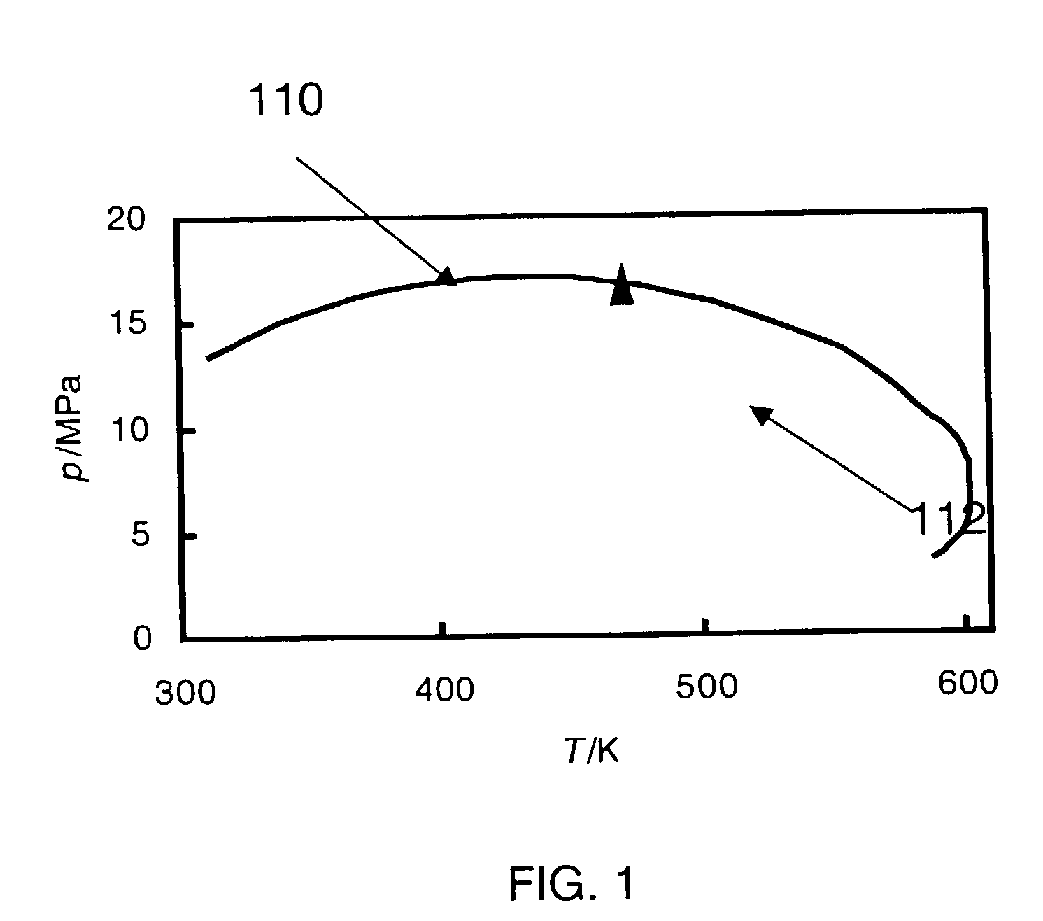
[0039]FIG. 1 shows an example plot in pressure and temperature of a phase border for an example fluid with composition shown in Table 1. The phase border shown in FIG. 1 was estimated using the program known as HASBRO. The triangle represents the critical condition. The portion of the curve on the left side of the triangle represents the bubble curve 110. The portion of the curve on the right side of the triangle represents the dew curve 112. Reservoir performance calculations greatly benefit from a knowledge of the location of the fluid (p, T, x) pressure-temperature-composition phase transitions. At either reservoir or producing zone conditions the most significant phase borders, shown in FIG. 1 for the mixture defined in table 1, are the formation of a liquid from a gas (dew point) and a gas from a liquid (bubble point). The phase behavior of black oils is dominated by the mole fraction of low molecular mass components, while for retrograde condensates the phase behavior is deter...


PUM


Abstract

A control system for a hydrocarbon well is also disclosed. A control valve system is used to control the flow of fluid being produced by the well. A real time sensor is provided downhole and is used to make real time measurements of phase characteristics of the fluid. A controller is used to control the valve system so as to reduce the risk of undesirable phase transitions in the fluid based on the real time measurements made by the sensor. The sensor includes an acoustic transducer configured to emit acoustic energy into the fluid at a level which causes a phase transition in the fluid. The controller determines the level of acoustic energy emitted into the fluid, and also determines the pressure associated with a phase transition using the level of emitted acoustic energy.

Description

REFERENCE TO PRIOR APPLICATIONS[0001]This is a divisional of U.S. patent application Ser. No. 10 / 206,499, which was filed Jul. 26, 2002 (now U.S. Pat. No. 6.758,090), which is a continuation-in-part of (1) U.S. patent application Ser. No. 09 / 459,054 (now U.S. Pat. No. 6,490,916), which was filed Dec. 10, 1999 and (2) U.S. patent application Ser. No. 09 / 094,811 (now U.S. Pat. No. 6,128,949), which was filed Jun. 15, 1998. U.S. patent application Ser. No. 09 / 459,054 claims priority to Great Britain Application No. 9828253.6, filed 23 Dec. 1998, now abandoned. All of these patent applications and their corresponding issued patents are incorporated by reference herein in their entireties.FIELD OF THE INVENTION[0002]The present invention relates to methods for downhole fluid analysis and real time production control of a well. More particularly, the invention relates to an improved method for analyzing thermodynamic phases of complex fluids downhole, and for using such analyses for real ...

Claims


Application Information

Patent Timeline
IPC IPC(8): E21B34/06E21B47/06E21B43/12E21B34/08E21B49/08G01N33/28
CPCE21B34/08E21B43/12G01N33/2823E21B49/081E21B49/08
Inventor GOODWIN, ANTHONY ROBERT HOLMESSTEPHENSON, KENNETH EDWARDODDIE, GARY MARTINKLEINBERG, ROBERT LEONARDGRIFFIN, DOUGLAS D.
Owner SCHLUMBERGER TECH CORP
Learn More