Arrangement and method for providing an air flow within an upholstered seat

an air flow and upholstered seat technology, applied in the field of arrangement and method of providing air flow within the upholstered seat, can solve the problems of compromising the physical integrity of the seat cushion structure, requiring considerable labor, and unable to retrofit seats with cooling devices, etc., and achieves the effect of rapid heating of the seat back or bottom

Inactive Publication Date: 2006-01-24
WITCHIE RONALD G
View PDF8 Cites 126 Cited by
  • Summary
  • Abstract
  • Description
  • Claims
  • Application Information

AI Technical Summary

Benefits of technology

[0012]The spacer layer is preferably soft and cushiony to provide a comfortable support for a person in the seat but resists collapse under the weight of the seated person or when the person leans against the seat back so as to maintain a substantial air flow path for the air from the blower outlet.
[0014]The mesh layer also has a serpentine pattern of insulated heating wire or other heating element attached thereto to enable rapid heating of the seat back or bottom when the heater elements are energized.

Problems solved by technology

This requires considerable labor and compromises the physical integrity of the seat cushion structure.
This also makes retrofitting of seats with the cooling device difficult.

Method used


Image

  • Arrangement and method for providing an air flow within an upholstered seat
  • Arrangement and method for providing an air flow within an upholstered seat
  • Arrangement and method for providing an air flow within an upholstered seat

Examples


Embodiment Construction

[0022]In the following detailed description, certain specific terminology will be employed for the sake of clarity and a particular embodiment described in accordance with the requirements of 35 USC 112, but it is to be understood that the same is not intended to be limiting and should not be so construed inasmuch as the invention is capable of taking many forms and variations within the scope of the appended claims.

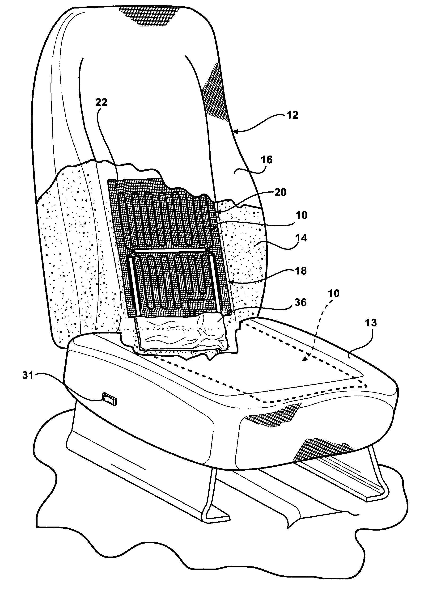
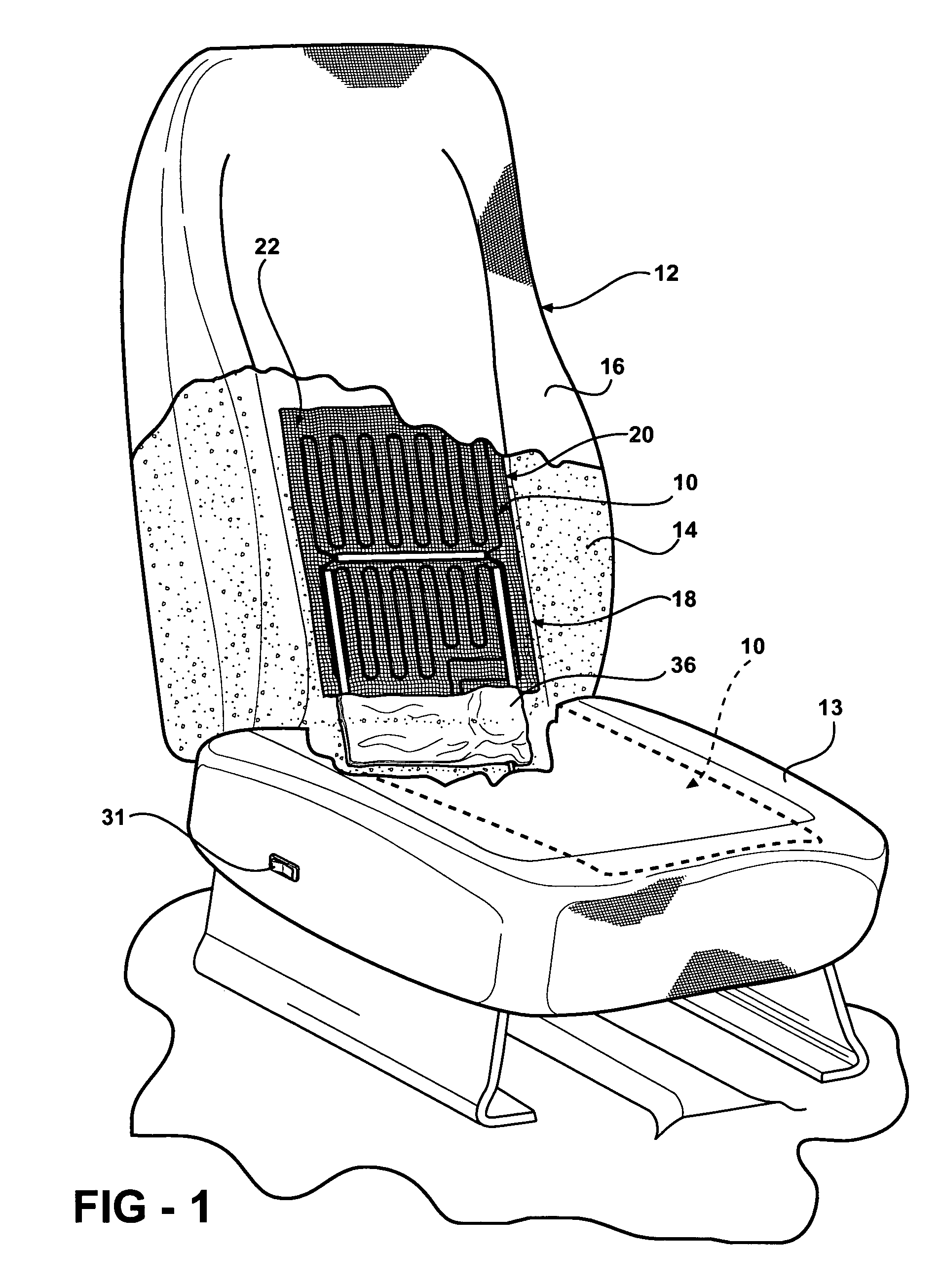
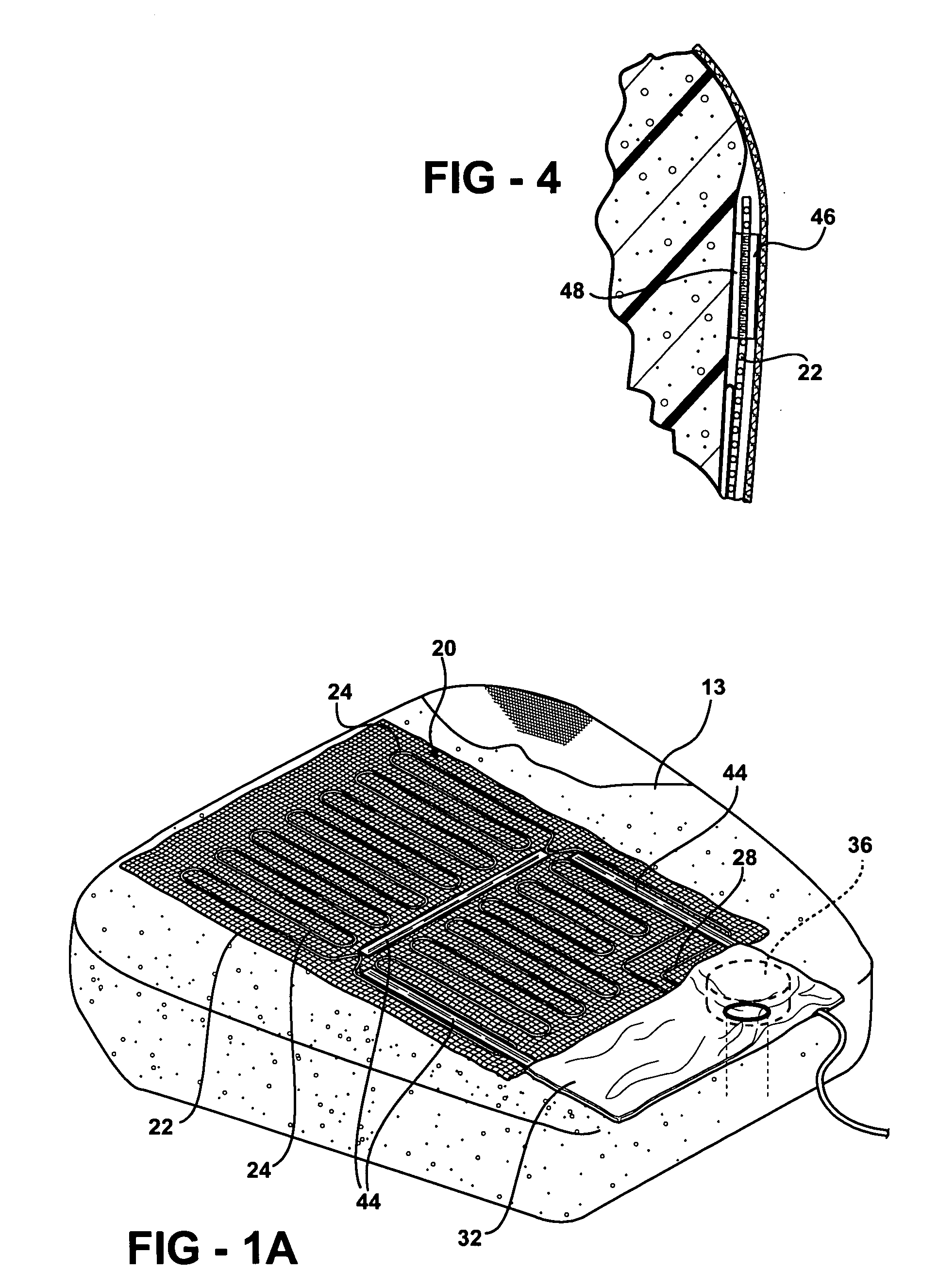
[0023]Referring to the drawings, the present invention comprises an arrangement for directing an air flow within an upholstered seat such as is used in automotive and other vehicles utilizing a generally rectangular insert 10 configured to be installed in the front of an upholstered seat back 12 beneath a seat cover 16. The insert 10 may also be installed beneath the cover of the upholstered seat bottom 13 in a similar fashion (see FIG. 1A). The insert 10 is positioned with its bottom adjacent the V-shaped space normally found at the convergency between the bottom of the...


PUM


Abstract

An arrangement and method for producing an air flow within an upholstered seat back or bottom in which a seat insert has a blower mounted in a pouch at the crotch region between the seat back and bottom and has an outlet which directs air flow up through a spacer layer so as to distribute air flow out through a porous seat back cover or beneath a nonporous cover. A solid plastic backing sheet underlies the spacer layer to direct all air flow out from the spacer layer, the plastic sheet also forming the blower pouch. A mesh layer is bonded to the plastic sheet and used to attach the insert to the seat cushion as well as to carry a heating element pattern extending thereover to also enable electrical heating of the seat back or bottom.

Description

CROSS REFERENCE TO RELATED APPLICATIONS[0001]This application claims the benefit of U.S. provisional Ser. No. 60 / 423,770, filed Nov. 5, 2002.BACKGROUND OF THE INVENTION[0002]This invention concerns devices for improving the comfort of a person occupying a seat, particularly suited for upholstered seats.[0003]Seat cooling arrangements have been developed involving air ducting or large plenum cavities carved out within the seat back foam cushion forming the support structure of the seat back (or bottom). This requires considerable labor and compromises the physical integrity of the seat cushion structure. This also makes retrofitting of seats with the cooling device difficult. See U.S. Pat. Nos. 6,059,018; 6,179,706; 6,505,996; 5,385,382; and 3,550,523 for examples of such installations.[0004]Air from the vehicle air conditioning is usually relied on to create seat cooling. The internal ducting is necessary in order to insure a distributed flow of air over most of the area of the seat...

Claims


Application Information

Patent Timeline
Patent Type & Authority Patents(United States)
IPC IPC(8): A47C31/00A47C7/74B60N2/56
CPCA47C7/744B60N2/5628B60N2/5657B60N2/5685B60N2/5635
Inventor WITCHIE, RONALD G.
Owner WITCHIE RONALD G
Why Eureka
Try Eureka