Ink jet recording head and ink discharge method

a recording head and ink jet technology, applied in printing and other directions, can solve the problems of low discharge efficiency, difficult displacement in the discharge direction, and errors in the discharge direction, and achieve the effect of reducing the number of liquid droplets and facilitating the discharge of comparatively small liquid droplets

Inactive Publication Date: 2006-01-24
CANON KK
View PDF22 Cites 29 Cited by
  • Summary
  • Abstract
  • Description
  • Claims
  • Application Information

AI Technical Summary

Benefits of technology

[0011]Now, the present invention is designed with a view to solving the problems discussed above. It is an object of the invention to provide an ink jet recording head capable of discharging comparatively small liquid droplets from the discharge ports efficiently with the enhanced precision of the discharge direction of liquid droplets to be discharged from the discharge ports, and also, to provide an ink discharge method.
[0015]Also, for the ink jet recording head of the present invention, it is preferable to make the center-to-center distance dhc between the respective two heat generating members, which are arranged to be apart from each other most among plural heat generating members, larger than the opening diameter do of the discharge port. In this manner, even if the central position of the discharge port and the central position of the pressure-generating area are slightly displaced, the liquid column of ink discharged from the discharge port is formed between the bubble generated by one heat generating member and the bubble generated by the other heat generating member. As a result, it is not allowed to be in contact with the sidewall faces of the discharge port. Then, the main ink droplet is discharged from the discharge port without any displacement in the discharge direction. Also, if the liquid column is not allowed to be in contact with the sidewall faces of the discharge port, the portion of the main liquid droplet, which is separated from the liquid column is constant, hence making it possible to stabilize the size of the dot to be formed on a recording sheet or the like by the placement of the main liquid droplet thereon.
[0016]Also, for the ink jet recording head of the present invention, it is preferable to satisfy the relations of dhc>do+2 derr where the dhc is the distance, the do is the opening diameter, and the derr is the amount of displacement, provided that the amount of displacement of the center of the discharge port to the extended line is given as derr. In this way, it is made possible to stabilize the placement position of the main liquid droplet, while placing the micro liquid droplets generated on the separated portion between the main liquid droplet and the liquid column also on the position where the main liquid droplet is placed. Thus, it becomes possible to stabilize the shape and position of the dot formed by the liquid droplets thus placed.

Problems solved by technology

As a result, the cut-off and separation of the main liquid droplet is executed in a state of being displaced from the center of the discharge port, and errors occur in the direction of discharge.
Therefore, it is required more than ever to make arrangement so that such displacement is not easily made in the discharge direction.
As a result, the amount of electric current that runs on the heat generating member is significantly increased, and the voltage drop is intensive due to parasite resistance on the wiring portion up to the heat generating member, leading to a problem that the discharge efficiency is lowered.
However, there is a limit to the increased value of resistance that may be attained by changing materials of the heat generating member.
Also, when a new material is used, it is necessary to obtain a sufficient verification to ascertain whether or not there is any functional problems when it is adopted, thus making it difficult to implement this preventive means.

Method used


Image

  • Ink jet recording head and ink discharge method
  • Ink jet recording head and ink discharge method
  • Ink jet recording head and ink discharge method

Examples


first embodiment

(First Embodiment)

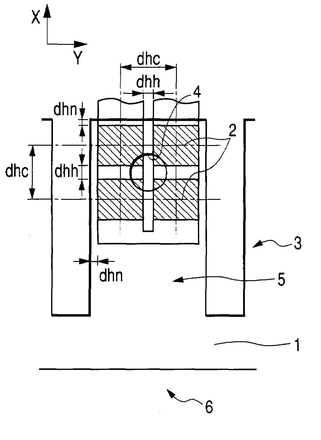
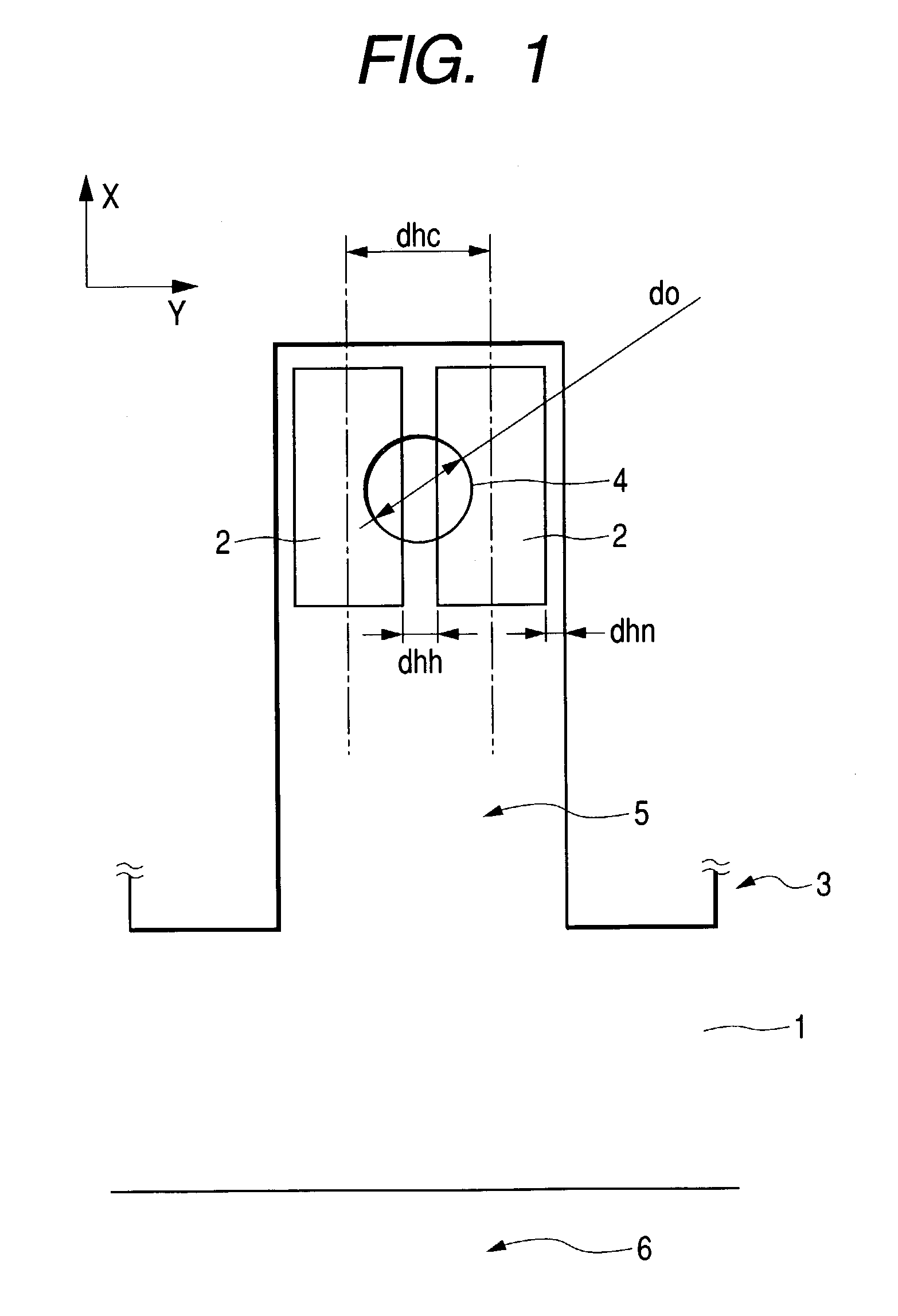
[0029]FIG. 1 is a perspective plan view that shows the relative arrangements of the ink flow path, the heat generating member, and the discharge port for an ink jet recording head in accordance with a first embodiment of the present invention.

[0030]The ink jet recording head of the present embodiment is provided with the substrate 1 having many numbers of heat generating members 2 on the surface thereof, and the flow path formation member 3, which is arranged on the substrate 1. The flow path formation member 3 is provided with the partition walls 3a that divide many numbers of heat generating members 2 into two members each; and the ceiling wall 3b that faces the substrate 1. The partition walls 3a form many numbers of ink flow paths 5 that supply ink to each of the pressure generating areas formed by two heat generating members 2 thus divided. Also, for each of the ink flow paths 5, the discharge port 4 is formed for the ceiling wall 3b on the extended line, whic...

second embodiment

(Second Embodiment)

[0043]FIGS. 4A and 4B are views that illustrate the relative arrangements of the ink flow path, the heat generating member, and the discharge port for an ink jet recording head in accordance with a second embodiment of the present invention. FIG. 4A is a plan view thereof; and FIG. 4B is a cross-sectional view thereof.

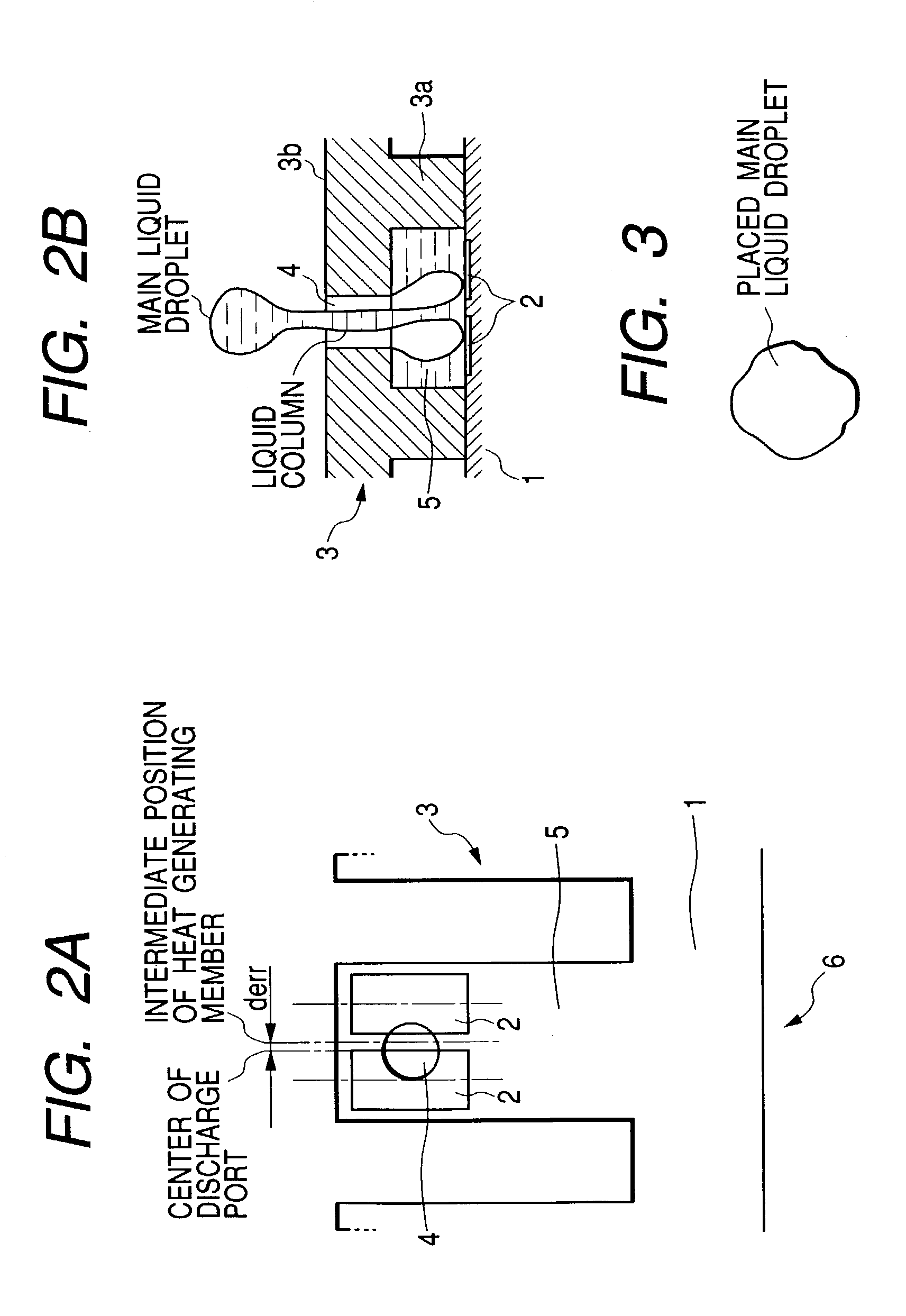
[0044]As shown in FIG. 4A, the ink jet recording head of the present embodiment is particularly provided with the pressure-generating area formed by one set of four heat generating members 2 in one ink flow path 5. With the assumption that these heat generating members 2 define the ink flow in ink flow path 5 as X direction toward the heat generating member 2 from the ink supply path 6 side, and the direction orthogonal to this X direction as Y direction, two of them are arranged in the X direction, and two of them in the Y direction, respectively. Also, these heat generating members 2 are electrically connected in series. The discharge port 4 is arr...

third embodiment

(Third Embodiment)

[0050]FIGS. 5A and 5B are views that illustrate the relative arrangements of the ink flow path, the heat generating member, the discharge port, and the non-heat generating area for an ink jet recording head in accordance with a third embodiment of the present invention.

[0051]The ink jet head of the third embodiment is different from the embodiments described above in that only one heat generating member 2 in the square form is arranged in one ink flow path 5. All other structures of the recording head of the present embodiment are almost the same as those of the first embodiment. For convenience' sake, therefore, the same reference marks are applied to the same members, and the description thereof will be omitted.

[0052]For the present embodiment, each of the heat generating members 2 is in a square of 26 μm wide×26 μm long, and the opening diameter do of the discharge port 4 is 16 μm. Also, as shown in FIGS. 5A and 5B, first and second protection films 7 and 8, and...


PUM


Abstract

An ink jet recording head is provided with one heat generating member in each of ink flow paths, and the discharge port thereof is arranged on the extended line extending in the normal direction from the center of the main surface of the heat generating member to the surface of the substrate. Then, on the surface of the substrate, non-bubbling area is provided on the center within the projected area having the discharge port projected thereon. Bubble brought to the boil by the heat generating member pushes out ink from the discharge port by the pressure exerted by the bubble, while being communicated with the outside. With the structure thus arranged, it is made possible to enhance the precision of discharge direction of the liquid droplet discharged from the discharge port.

Description

BACKGROUND OF THE INVENTION[0001]1. Field of the Invention[0002]The present invention relates to an ink jet recording head for recording by discharging ink to a recording medium. The invention also relates to an ink discharge method.[0003]2. Related Background Art[0004]In recent years, it has become easier for an ink jet recording apparatus to obtain high-quality characters and images. The ink jet recording apparatus has been widely used as the output equipment for a computer in particular. Among such apparatuses, the one that adopts the bubble jet method, in which ink is discharged from the nozzle by means of abrupt changes of pressure exerted with quick boiling given to ink in the nozzle, makes it easier to arrange a number of nozzles in high density with a simple structure, hence becoming the main stream of the ink jet recording apparatuses.[0005]Further, in recent years, along with the wider use of the ink jet recording apparatus, there have been more demands in a higher perform...

Claims


Application Information

Patent Timeline
Patent Type & Authority Patents(United States)
IPC IPC(8): B41J2/135B41J2/05B41J2/14
CPCB41J2/1404B41J2/14056B41J2/1412B41J2/14129B41J2002/14387B41J2002/14177B41J2002/14185
Inventor KANEKO, MINEOTSUCHII, KENTSUKUDA, KEIICHIROOIKAWA, MASAKIYABE, KENJI
Owner CANON KK
Why Eureka
Try Eureka