Hand-guided electric tool comprising a guard

a technology of guards and electric tools, which is applied in the direction of manufacturing tools, instruments, metal-working machine components, etc., can solve the problems of time-consuming process, inability for users to remove the support flange, and the inability to use the guard hood in connection with a particular tool diameter, etc., and achieve the effect of small diameter

Inactive Publication Date: 2006-01-24
ROBERT BOSCH GMBH
View PDF7 Cites 62 Cited by
  • Summary
  • Abstract
  • Description
  • Claims
  • Application Information

AI Technical Summary

Benefits of technology

[0003]An electrical tool according to the invention has the advantage over the prior art that the guard hood provided with the features according to the invention can also be mounted on an electrical tool, a particular a right angle grinder, whose support flange cannot be removed and in which the support flange diameter is only slightly smaller than the diameter of the machine's receiving collar for the guard hood. This is made possible by virtue of the fact that the clamping strap is slid with its recess over the protrusion of the receiving collar until it is situated entirely beneath the protrusion and is then rotated around the drive axis in relation to the receiving collar, and by virtue of the fact that the guard hood has no elements, which have a smaller diameter than that of the receiving collar. As a result, beneath the protrusion, there is a region of the clamping strap in which the clamping strap does not have any recess. Consequently, the guard hood is prevented from moving out of the way in the axial direction. The free rotation of the clamping strap in relation to the receiving collar is assured by virtue of the fact that the width of the clamping strap corresponds approximately to the distance between the protrusion and the housing.
[0004]It is advantageous if the protrusion and the recess are disposed so that the guard hood can be slid over the protrusion only in a position in which it does not make sense to operate the electrical tool. This prevents the guard hood from unintentionally coming off when it is in the working position, even when the clamping element is released. This increases user safety and reduces the risk of injury.
[0005]It is also advantageous if the protrusion and / or the recess are the shape of circular segments in the axial direction of the spindle axle. Such a design is particularly easy to produce and is also safe to use.
[0006]It is also advantageous if the clamping element forms recess. As a result, the clamping element can be used to slide over the protrusion on the receiving collar. Such an embodiment is particularly easy to produce since the clamping element is as a rule embodied as a moving part, which is particularly easy to provide with such a shape.
[0008]It is also advantageous if the protrusions and recesses each have different, reciprocally matched sizes and / or distances from one another. This makes it possible to produce still more variations for the coding of the guard hood since both the sizes and the distances can be varied.
[0009]It is also advantageous if the electrical tool has a support flange, which is disposed concentrically around the spindle axle and whose diameter is only slightly smaller than that of the receiving collar. This assures a good support of the insert tool, wherein the contact surface on the support flange is enlarged in relation to the prior art. Previously, because of the projections pointing inward from the clamping strap, either the support flange had to be significantly smaller than the receiving collar or else the support flange had to be removed in order to install the guard hood.

Problems solved by technology

As a result, a guard hood with a particular diameter can only be used in connection with a particular tool diameter.
As a result, in order to mount the guard hood on the right angle grinder, it is first necessary to remove the support flange since the internal projections of the clamping strap do not fit over the support flange.
This is a very time-consuming process.
In right angle grinders that have a quick-action attachment in the support flange, it is impossible for the user to remove the support flange.
Such devices cannot be equipped with guard hoods that have a projection oriented toward the machine.

Method used


Image

  • Hand-guided electric tool comprising a guard
  • Hand-guided electric tool comprising a guard
  • Hand-guided electric tool comprising a guard

Examples


Embodiment Construction

[0019]In the following, identical parts are provided with the same reference numerals.

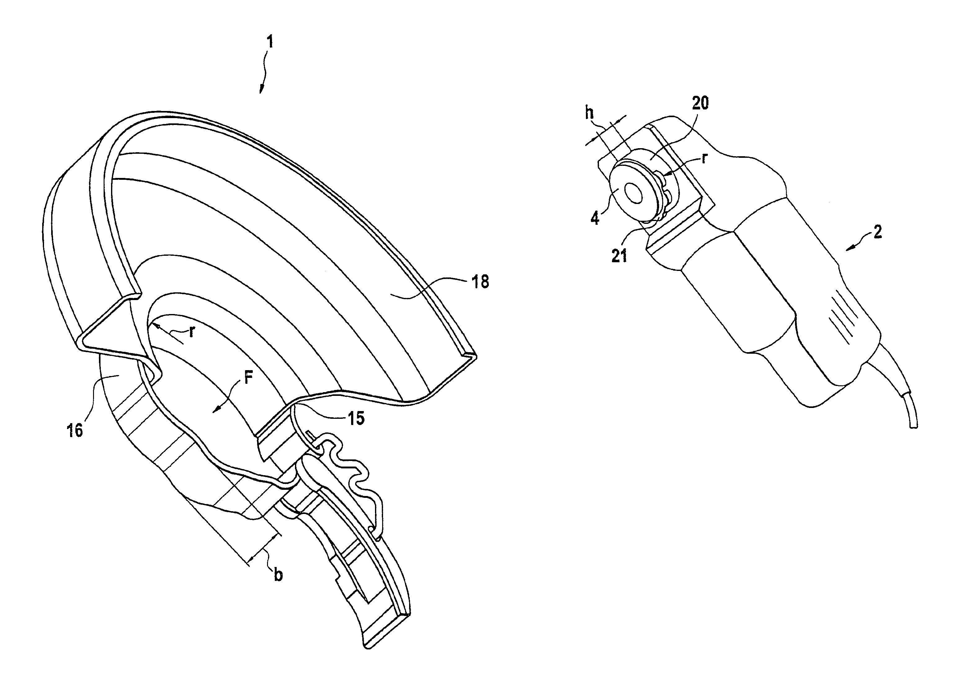
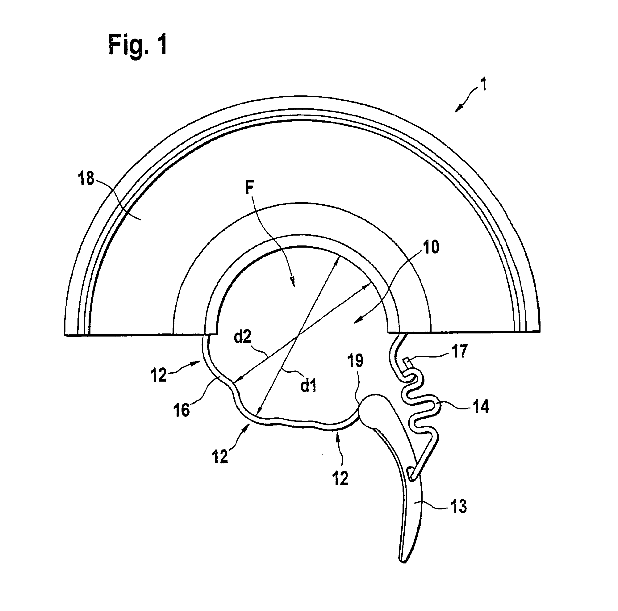
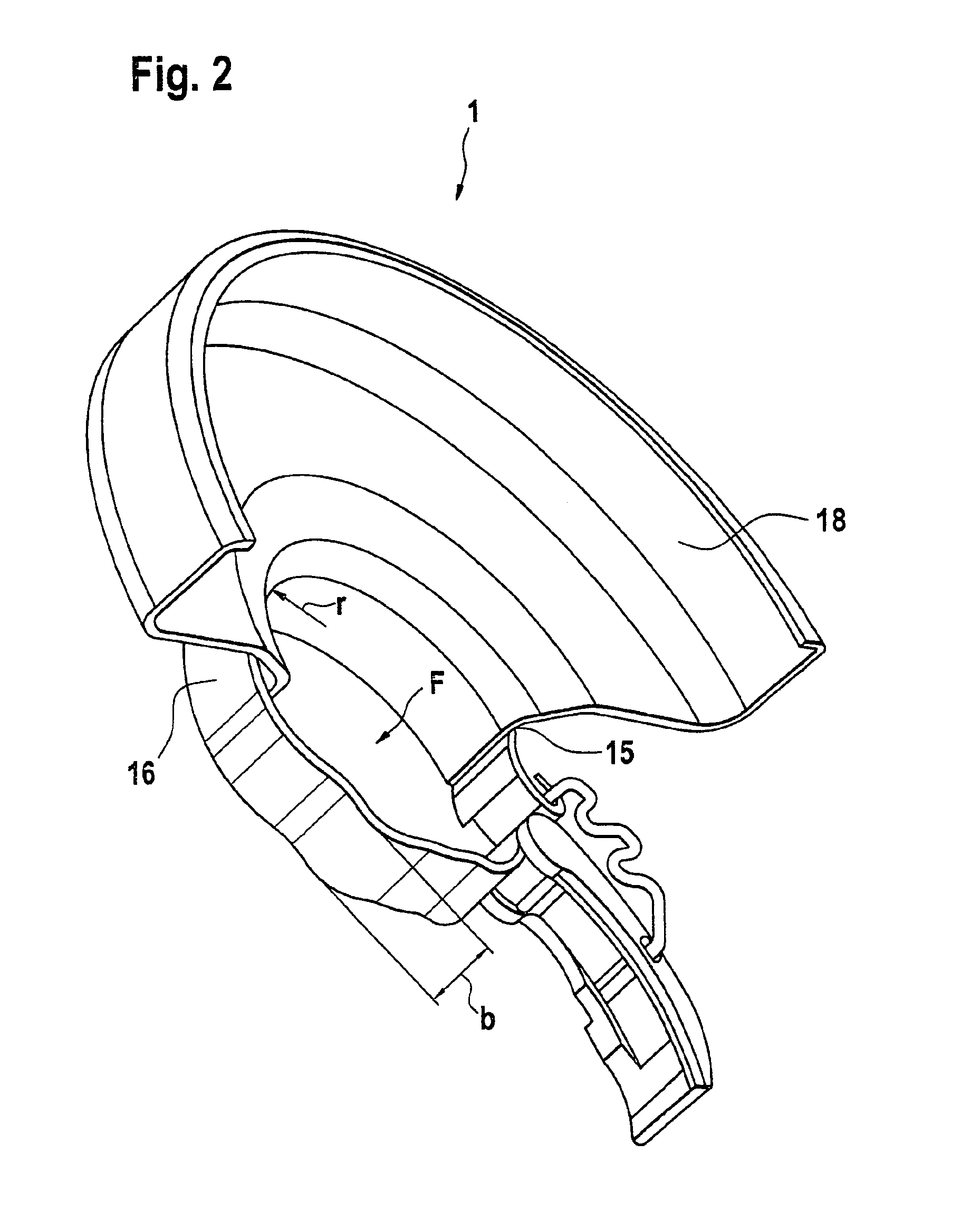
[0020]FIGS. 1 and 2 show two views of a guard hood 1 for a hand-guided electrical tool 3, in the current instance a right angle grinder (FIGS. 5 to 8). The guard hood 1 has a flat, semicircular hood part 18, to which a clamping strap 16 is attached by means of a transition 15 so that between the clamping strap 16 and the hood part 18, an opening 10 is formed. This opening 10 has a changeable area F. A clamping element 13, 14 is affixed to the clamping strap 16 in order to change the area F. The clamping strap 13, 14 here is comprised of a clamping lever 13, which is rotatably supported on a first end 19 of the clamping strap 16, and, by means of a spring 14 rotatably supported on the clamping lever 13, cooperates with a second end 17 of the clamping strap 16. The second end 17 is curved so that it forms a counterpart support for the spring 14. When the clamping lever 13 is rotated, this changes the...


PUM


Abstract

In a hand-guided electrical tool 3 with a housing 2 that has a receiving collar 20 embodied on it and with a guard hood 1 that can be attached to the receiving collar 20 and has a clamping strap 16, which can move freely around the receiving collar 20 in a first position and rests snugly against the receiving collar 20 in a second position, a secure connection between the guard hood 1 and the housing 2 is achieved by virtue of the fact that the receiving collar 20 has at least one protrusion 21, which protrudes beyond the second area in the radial direction away from the spindle axle 5, and between the protrusion 21 and the housing 2, there is a distance h, which approximately corresponds to the width b of the clamping strap 16, and by virtue of the fact that that the clamping strap 16 has at least one indentation 12 so that the first diameter d1 of the opening 10 of the clamping strap 16 in the vicinity of the indentation 12 is greater than the second diameter d2 in the remaining region, wherein the first diameter d1 is of such a size that the clamping strap 16 can be moved over the protrusion 21 and the second diameter d2 is of such a size that the clamping strap 16 cannot be moved over the protrusion 21.

Description

BACKGROUND OF THE INVENTION[0001]The invention is based on a hand-guided electrical tool with a housing and a guard hood.[0002]Right angle grinders with a guard hood are known, whose clamping strap has a projection on the inside. The clamping strap of the guard hood can be attached to a receiving collar, which is disposed around a spindle axle for a rotating insert tool. The projection engages in a groove in the receiving collar of the machine. As a result, the projection assures that the guard hood does not detach from the receiving collar during operation. This is also the case even if the locking element, which presses the clamping strap against the receiving collar, opens. This increases the safety of the right angle grinder and reduces the risk of injury that it represents since the guard hood cannot fall off. For example, it is known to use screws, quick-action levers, or the like as locking elements. It is also known to bring projections of different widths on the clamping st...

Claims


Application Information

Patent Timeline
Patent Type & Authority Patents(United States)
IPC IPC(8): B24B23/00B23Q1/01B23Q11/06B24B23/02B24B55/05
CPCB23Q1/017B24B55/052B24B23/02B23Q11/06
Inventor HOFMANN, ALBRECHTKRONDORFER, HARALDHECKMANN, MARKUSSCHOMISCH, THOMAS
Owner ROBERT BOSCH GMBH
Why Eureka
Try Eureka