Apparatus and method for filtering particulate and reducing NOx emissions

a technology of particulate filter and nox emission, which is applied in the direction of machines/engines, chemical/physical processes, surface coverings, etc., can solve the problems of cracking and melting of the traps, loss of energy, and pressure drop across the traps, so as to reduce the weight of the filter structure, increase the engine fuel consumption, and reduce the effect of sulfur fuel

Inactive Publication Date: 2006-01-24
ILLINOIS VALLEY HLDG
View PDF7 Cites 66 Cited by
  • Summary
  • Abstract
  • Description
  • Claims
  • Application Information

AI Technical Summary

Benefits of technology

[0025]The subject invention uses monolithic porous wall ceramic traps of either the cross flow or the wall flow type that will collect the soot and ash with an efficiency of 95–98%. The pressure drop across the trap increases as the soot and ash accumulate and the traps must be periodically regenerated. However, in this invention the soot and ash are removed physically by reverse flow of pre-filtered exhaust gas at normally encountered exhaust gas pressures and flow rates and the soot a

Problems solved by technology

While these traps remove 95–98% of the particulate, pressure drop across the traps builds up due to the accumulation of soot and ash.
While the soot can be burned away by heating all, or a portion, of the exhaust gas, loss of energy occurs and, more seriously, the heat of the combustion of the soot leads to cracking and melting of the traps.
In addition, the incombustible ash must be periodically removed by a disruptive and expensive cleaning operation.
Finally, these systems are also subject to plugging by incombustible ash.
Whil

Method used


Image

  • Apparatus and method for filtering particulate and reducing NOx emissions
  • Apparatus and method for filtering particulate and reducing NOx emissions
  • Apparatus and method for filtering particulate and reducing NOx emissions

Examples


Embodiment Construction

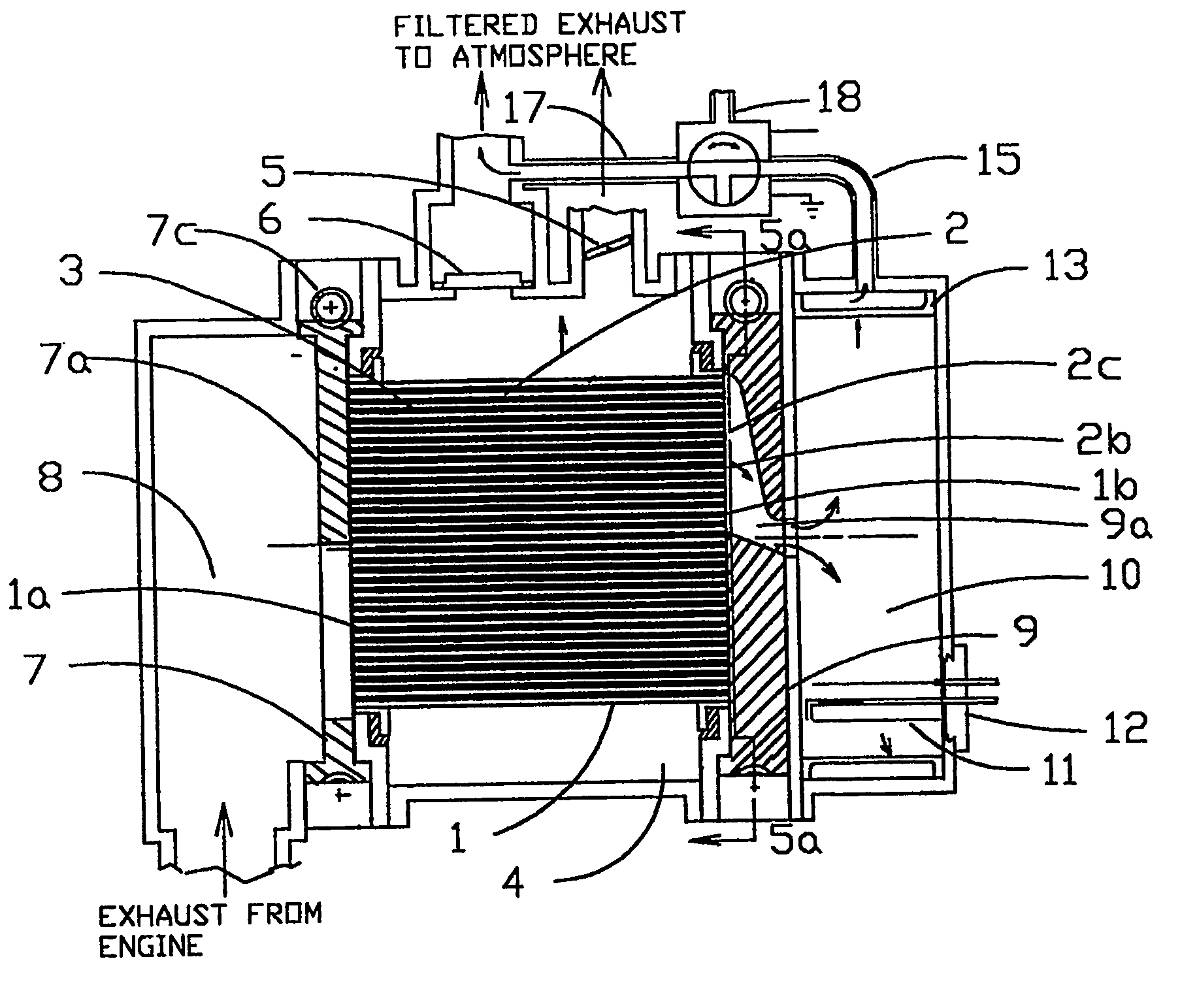
[0090]The current invention relates to a particulate trap system that uses either cross flow or wall flow traps and has means for accomplishing reverse flow of the exhaust gas as well as through flow of the exhaust gas to dislodge, erode and remove the soot and ash build-up at temperatures below the ignition point of soot and at pressures and flow rates normally encountered in internal combustion engines, thereby resulting in minimal adverse effects on engine performance. The particulate trap system accomplishes the regeneration or removal of the soot and ash build-up by reverse flow or a combination of reverse flow and through flow to dislodge and erode the soot and ash build-up through a physical or mechanical mechanism, without the addition of heat to burn the soot. The invention eliminates the need for high temperatures and / or the use of expensive catalysts. The ignition of the soot and subsequent combustion of the ash take place in a separate, small and robust chamber. An advan...


PUM

PropertyMeasurementUnit
Temperatureaaaaaaaaaa

Abstract

An apparatus and method for filtering particulate from an internal combustion engine by use of monolithic particulate trap systems having porous walls (2c, 24c). The porous walls (2c, 24c) filter the particulate. The filtered particulate on inner surfaces of the porous walls is periodically removed or regenerated via back flow of previously filtered exhaust gas. The back flow is caused by creating a pressure difference across the porous walls. The back flow of the previously filtered exhaust gas is simultaneously or sequentially coupled with high velocity through flow of exhaust gas in the channels. In addition, the particulate trap system can be an adsorber-catalyst particulate trap system for filtering particulate and reducing NOx via an adsorber-catalyst trap systems to achieve the EPA 2007 standards.

Description

CROSS REFERENCE TO RELATED APPLICATIONS[0001]This application is 371 of PCT Application No. PCT / US02 / 40107 filed 16 Dec. 2002 which named the United States as a designated country and claims priority of U.S. Application No. 60 / 372,238, filed 12 Apr. 2002, entitled Particulate Trap and NOx Adsorber-Catalyst Diesel Exhaust Aftertreatment System.TECHNICAL FIELD OF THE INVENTION[0002]The present invention relates generally to the field of diesel or other internal combustion engine exhaust systems, and more specifically, to an apparatus and method for reducing the release of emissions and particulate in the atmosphere, and to an apparatus and method for regenerating exhaust traps by reverse flow of filtered exhaust gas through porous walls of a plurality of tubular passages. The invention also relates to apparatus and method for using adsorption-catalyst technology to reduce NOx emissions when ultra low sulfur fuel becomes available.DESCRIPTION OF THE RELATED ART[0003]Diesel and other in...

Claims


Application Information

Patent Timeline
IPC IPC(8): B01D46/00B01D53/04B01D53/94F01N3/02B01D46/24F01N3/022F01N3/023F01N3/025F01N3/027F01N3/031F01N3/035F01N3/08F01N3/20F01N3/28F01N3/38F01N11/00F01N13/02F01N13/04
CPCB01D46/0058F01N13/0097B01D46/2418B01D53/9431B01D53/944F01N3/0222F01N3/0233F01N3/0235F01N3/025F01N3/0275F01N3/031F01N3/035F01N3/0814F01N3/0821F01N3/0842F01N3/0885F01N3/2033F01N3/2093F01N3/2828F01N3/38F01N11/00F01N13/017B01D46/0067B01D46/2455B01D2279/30F01N2240/02F01N2240/06F01N2330/06F01N2470/30F01N2510/06F01N2550/10F01N2550/12F01N2560/02F01N2610/03Y02T10/26Y02T10/47F01N2590/08Y10S55/30Y10S55/10B01D46/90B01D46/70Y02T10/12Y02T10/40
Inventor BAILEY, JOHN M.WALDMAN, DONALD J.WALDMAN, MARIANNE F.
Owner ILLINOIS VALLEY HLDG
Why Eureka
Try Eureka