Method of making at least one hole in a transparent body and devices made by this method

a technology of transparent body and laser drilling, which is applied in the direction of optical elements, manufacturing tools, instruments, etc., can solve the problems of relatively long process and human health hazards, and achieve the effect of improving the micromachining speed of optically transparent materials

Inactive Publication Date: 2006-01-24
CORNING INC
View PDF9 Cites 20 Cited by
  • Summary
  • Abstract
  • Description
  • Claims
  • Application Information

AI Technical Summary

Benefits of technology

[0006]One advantage of the method according to the present invention is an improved micromachining speed of optically transparent materials. Another advantage is that this method does not utilize acids to etch optically transparent materials.

Problems solved by technology

However, this process is relatively long because it utilizes two consecutive steps and the exposure to acid can be hazardous to human health.

Method used


Image

  • Method of making at least one hole in a transparent body and devices made by this method
  • Method of making at least one hole in a transparent body and devices made by this method
  • Method of making at least one hole in a transparent body and devices made by this method

Examples


Embodiment Construction

[0042]Reference will now be made in detail to the present preferred embodiments of the invention. These embodiments are illustrated in the accompanying Figures.

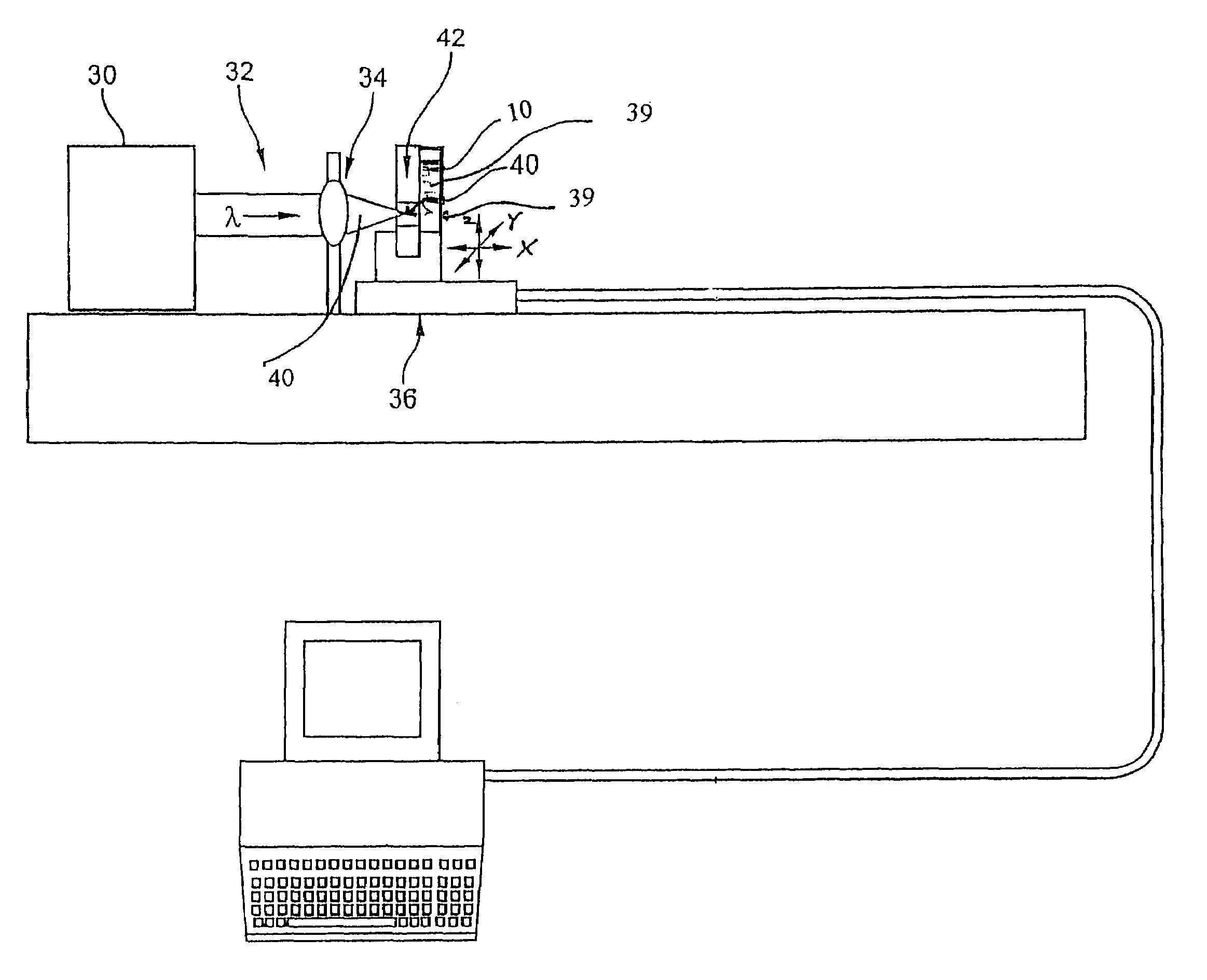
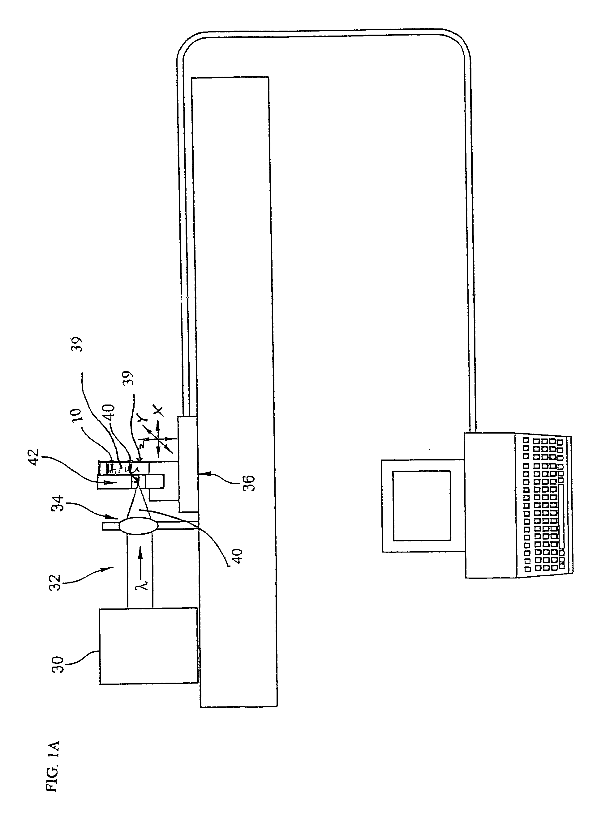
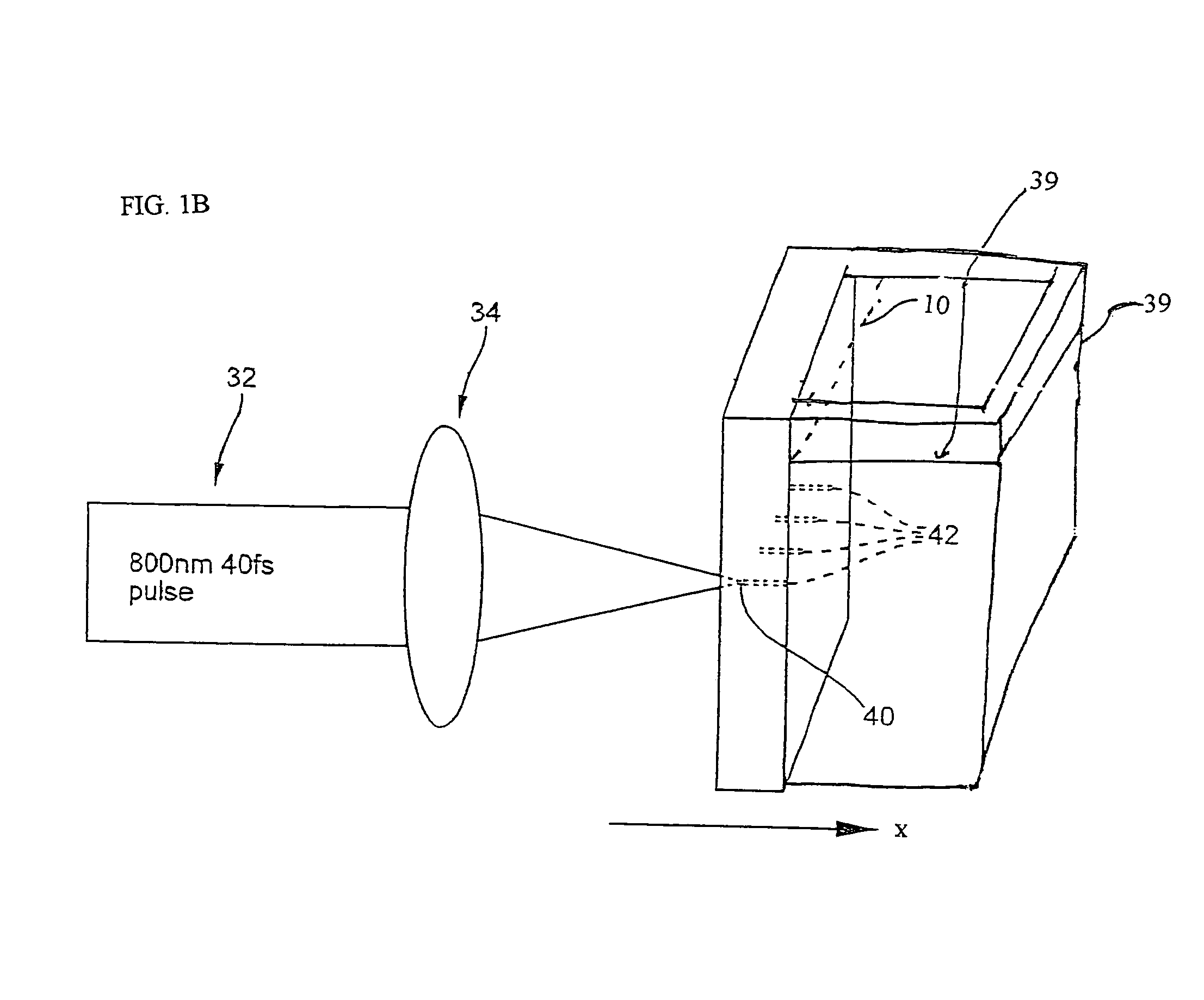
[0043]The invention relates to a method of wet laser drilling of transparent bodies 10 such as, for example, glass or sapphire. This method may be advantageously used for making optical devices described further down in the specification. The optical devices may be, for example, optical fiber devices for holding optical fibers, such as optical fiber ferrules.

[0044]As shown in FIGS. 1A–1C, the method includes providing an ultrashort pulse laser 30 for producing a laser output 32 with a wavelength λ with the laser output having a subpicosecond laser pulse duration. It is preferable that the optically transparent body 10 has a λ transparency of at least 90% / cm and preferably ≧95% / cm, preferably with an absorption at λ which is −2 cm−1. Preferably, optically transparent body has a bulk thickness of at least 0.5 mm, more preferabl...


PUM

PropertyMeasurementUnit
widthaaaaaaaaaa
widthaaaaaaaaaa
widthaaaaaaaaaa

Abstract

A method of making an at least one hole in an optically transparent body comprises the following steps: (i) providing an ultrashort pulse laser for producing a laser output with a wavelength λ, the laser output having a subpicosecond laser pulse duration; (ii) providing a laser output focusing lens for focusing the laser output, the focusing lens having a numerical aperture NA; (iii) providing an optically transparent body, the optically transparent body having a transparency at λ of at least 90% / cm; (iv) providing a liquid filled container situated proximate to the optically transparent body, such that the optically transparent body is in direct contact with the liquid; and (v) directing the laser output through the focusing lens to produce a focused laser output with a subpicosecond laser pulse duration proximate the optically transparent body, wherein the focused laser output traces at least one hole track pattern through the transparent glass body while the optically transparent body and said focused laser output move relative to one another in X-Y-Z directions. The at least one hole track pattern is in contact with the liquid and the focused laser output, in conjunction with the liquid, creates at least one hole in the optically transparent body.

Description

CROSS-REFERENCE TO RELATED APPLICATIONS[0001]This application claims the benefit of, and incorporates by reference, U.S. application Ser. No. 10 / 183,879, filed Jun. 25, 2002, entitled METHOD OF MAKING OPTICAL FIBER DEVICES AND DEVICES THEREOF by N. F. Borrelli, J. F. Schroeder, A. Streltsov and E. F. Murphy, which claims priority from the U.S. Provisional Application, Ser. No. 60 / 303,765, filed Jul. 6, 2001 entitled METHOD OF MAKING OPTICAL FIBER DEVICES AND DEVICES THEREOF, by N. F. Borrelli, J. F. Schroeder, A. Streltsov and E. F. Murphy.BACKGROUND OF THE INVENTION[0002]The present invention relates generally to a method of wet laser drilling of transparent materials and devices made by this method. The method is suitable for making of optical fiber devices.[0003]In the optical communications field of optical fibers and photonic devices, it is desirable to have optical fibers precisely held and positioned in a photonic material device. Optical communications devices often require ...

Claims


Application Information

Patent Timeline
Patent Type & Authority Patents(United States)
IPC IPC(8): G02B6/00C03C15/00C03C17/00B23K26/06B23K26/12B23K26/18B23K26/38B23K26/40C03B21/06C03B23/02C03B37/012C03C23/00G02B6/36
CPCB23K26/0639B23K26/009B23K26/0665B23K26/121B23K26/18B23K26/383B23K26/409C03B21/06C03B23/02C03C23/0025G02B6/3636G02B6/3644B23K26/0648G02B6/3652G02B6/3672G02B6/3688B23K26/40B23K26/064B23K26/1224B23K26/384B23K2103/172
Inventor SCHROEDER, JOSEPH FSTRELTSOV, ALEXANDER
Owner CORNING INC
Why Eureka
Try Eureka