Optical wireless networks with adjustable topologies

a wireless network and topology technology, applied in the field of dynamic reconfigurable communication networks, can solve the problems of limited data rate, limited range, and inability to meet the needs of users,

Active Publication Date: 2006-01-24
MARYLAND UNIV OF +1
View PDF4 Cites 38 Cited by
  • Summary
  • Abstract
  • Description
  • Claims
  • Application Information

AI Technical Summary

Problems solved by technology

Although OW test systems of this sort were developed in the 1960's, the technology was not widely accepted.
Radio frequency (RF) wireless systems may be used as a solution to the bridging problem, however they are limited in data rate due to the low carrier frequencies involved.
However, this generally limits the range to a few tens of meters.
The problem is, however, to provide these capacities to actual subscribers, who in general do not have direct fiber access to the network.
Cable modems are able to provide access at rates of about 30 Mb / s, however multiple subscribers must share a cable, and simultaneous usage by more than a few subscribers drastically reduces the data rates available to each.
The bridging problem possibly may be solved by laying optical fiber to each subscriber, yet this would be without the demand for the service from enough subscribers, the various communications service providers are generally unwilling to commit to the investment involved which is estimated at $1,000.00 per household.
The RF spectrum is becoming increasingly crowded and demand for available bandwidth is growing rapidly.
Recent research has shown that multi-hop, RF wireless networks, i.e., RF peer-to-peer or “infrastructure-less” networks are generally not scalable, and the size and number of users is limited.
A fundamental difficulty arises in the use of directed beams to communicate information between opposing nodes of a communication network in that the communication between nodes is terminated if the directed beam is obscured or obstructed.

Method used


Image

  • Optical wireless networks with adjustable topologies
  • Optical wireless networks with adjustable topologies
  • Optical wireless networks with adjustable topologies

Examples


Embodiment Construction

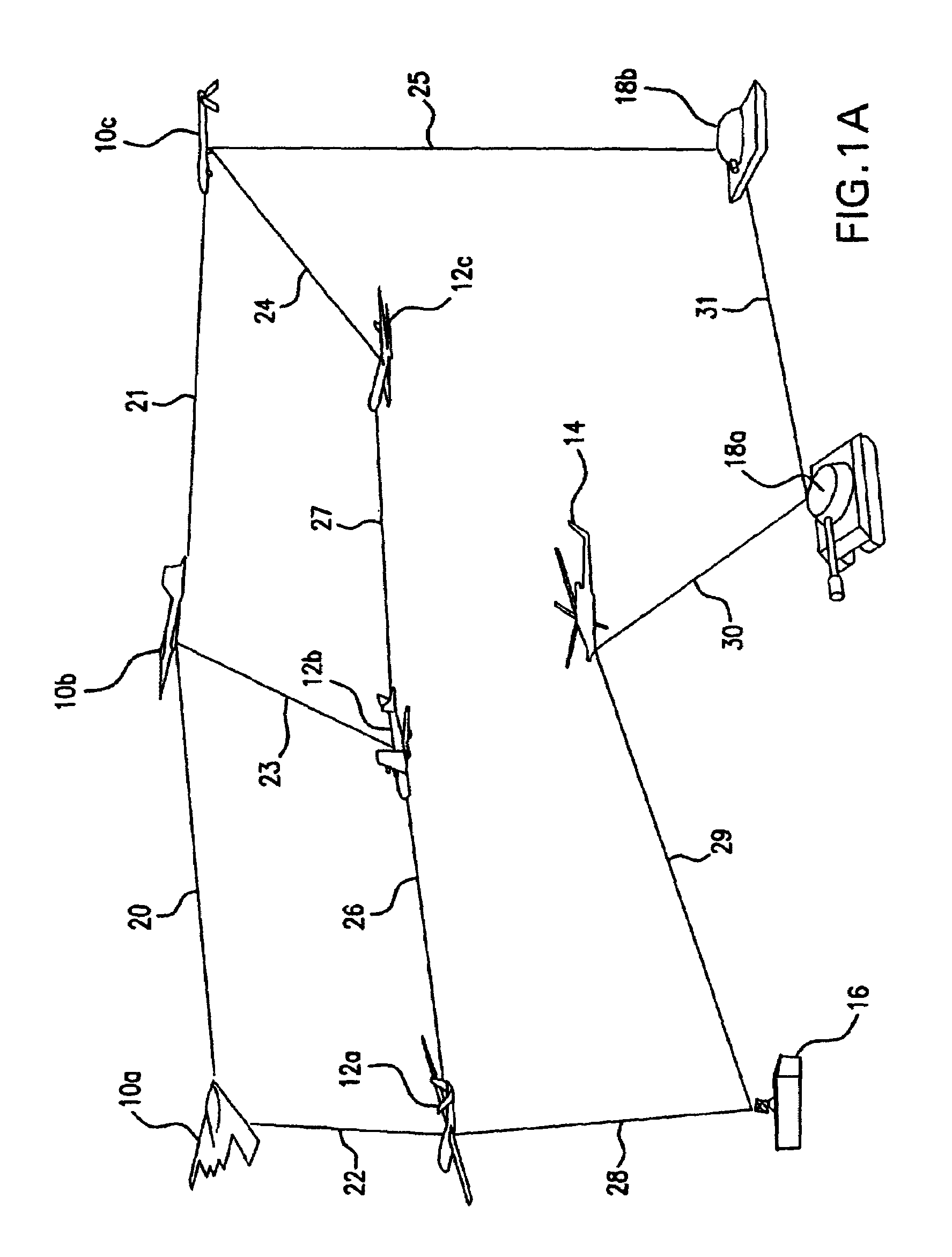
[0018]Referring to FIG. 1A, there is shown an exemplary embodiment of a communication network for which the method of the present invention provides substantial benefit. FIG. 1A represents various equipment that may compose a military combat setting. While the present invention has a much broader field of application than the illustrated military combat setting (such as providing a solution to the last mile problem discussed above), combat communications pose particular problems for which the present invention is well adapted. First, inter-vehicular communication on the field of combat should be secure to avoid unwanted enemy surveillance thereof. The present invention makes use of directed beams of electromagnetic radiation, such as beams of laser light, for carrying an information signal between the nodes of the network. By conveying network traffic on the directed beams between network nodes, the information carried thereon is not broadcast and is shared only between the two node...


PUM


Abstract

In a free space communication network in which different communication nodes are linked together by directed beams, a method for dynamically configuring the topology of the network allows the transmission directions of the communication nodes to be autonomously changed to communicate with a new node as dictated by the needs of the network. Moreover, the nodes can be switched from directional to broadcast and back again on an as-needed basis. The network consists of a topology that can be rapidly and physically reconfigured as required to provide multiple connectivity, a desired quality of service, or to compensate with the loss of communication links between nodes. The loss of direct communication between any two nodes in an optical network can occur because of obscuration of the atmospheric path between the two nodes. The directed beam which provides the communication channel between the two nodes can, in this situation, be steered to direct its energy towards another accessible node.

Description

[0001]This application claims the benefit of Provisional Application No. 60 / 394,521, filed Jul. 9, 2002.STATEMENT REGARDING FEDERALLY SPONSORED RESEARCH OR DEVELOPMENT[0002]The development of the invention described herein was funded by the U.S. Government through Contract DAAB0701CKZ17 granted by the U.S. Army and through ContractF306020020510 granted by the U.S. Air Force Research Lab. The U.S. Government has certain rights in this invention.FIELD OF THE INVENTION[0003]This invention relates to dynamically reconfigurable communication networks. More specifically, the present invention is directed to communication networks wherein the communication links thereof are established over a plurality of directed beams and wherein the physical topology thereof can be reconfigured by redirecting any of the directed beams of a node to a new node in the communication network.BACKGROUND OF THE INVENTION[0004]Direct line-of-sight optical communications has a long history. The use of directed b...

Claims


Application Information

Patent Timeline
Patent Type & Authority Patents(United States)
IPC IPC(8): H04Q7/20H04L12/56H04W40/06H04W40/24H04W84/18
CPCH04W40/06H04W84/18H04W40/24Y02D30/70
Inventor DAVIS, CHRISTOPHER C.MILNER, STUART D.SMOLYANINOV, IGOR I.
Owner MARYLAND UNIV OF
Why Eureka
Try Eureka