
Flexible printed circuit board and foldable cell phone terminal

a printed circuit board and cell phone terminal technology, applied in the direction of electrical apparatus casings/cabinets/drawers, cross-talk/noise/interference reduction, substation equipment, etc., can solve the problems of device noise source, reduced durability against folding and unfolding of body casings, and increased difficulty in arranging flexible printed circuit boards in body casings. , to achieve the effect of convenient arranging and convenient shielding

Inactive Publication Date: 2006-01-24
PANASONIC INTELLECTUAL PROPERTY CORP OF AMERICA
View PDF18 Cites 27 Cited by
  • Summary
  • Abstract
  • Description
  • Claims
  • Application Information

AI Technical Summary

Benefits of technology

[0005]An object of the present invention is to provide a flexible printed circuit board that can be arranged easily in a narrow width, and to provide a folding-type cellular telephone terminal employing such a flexible printed circuit board. Another object of the present invention is to provide a flexible printed circuit board that can be shielded easily, and to provide a folding-type cellular telephone terminal employing such a flexible printed circuit board.

Problems solved by technology

This makes it increasingly difficult to arrange the flexible printed circuit board in the body casings.
This leads to lower durability against the folding and unfolding of the body casing.
Moreover, a device, such as a folding-type cellular telephone terminal, that employs digital circuits and thus uses a clock pulse, tends to emit pulse noise, making the device a noise source.
Moreover, the flexible printed circuit board itself may act as an antenna, receiving noise being radiated through the air and propagating it to the other circuit boards.
Such noise can be suppressed by shielding the flexible printed circuit board, but it is not easy to shield it, since it is bent frequently.

Method used


Image

  • Flexible printed circuit board and foldable cell phone terminal
  • Flexible printed circuit board and foldable cell phone terminal
  • Flexible printed circuit board and foldable cell phone terminal

Examples


Embodiment Construction

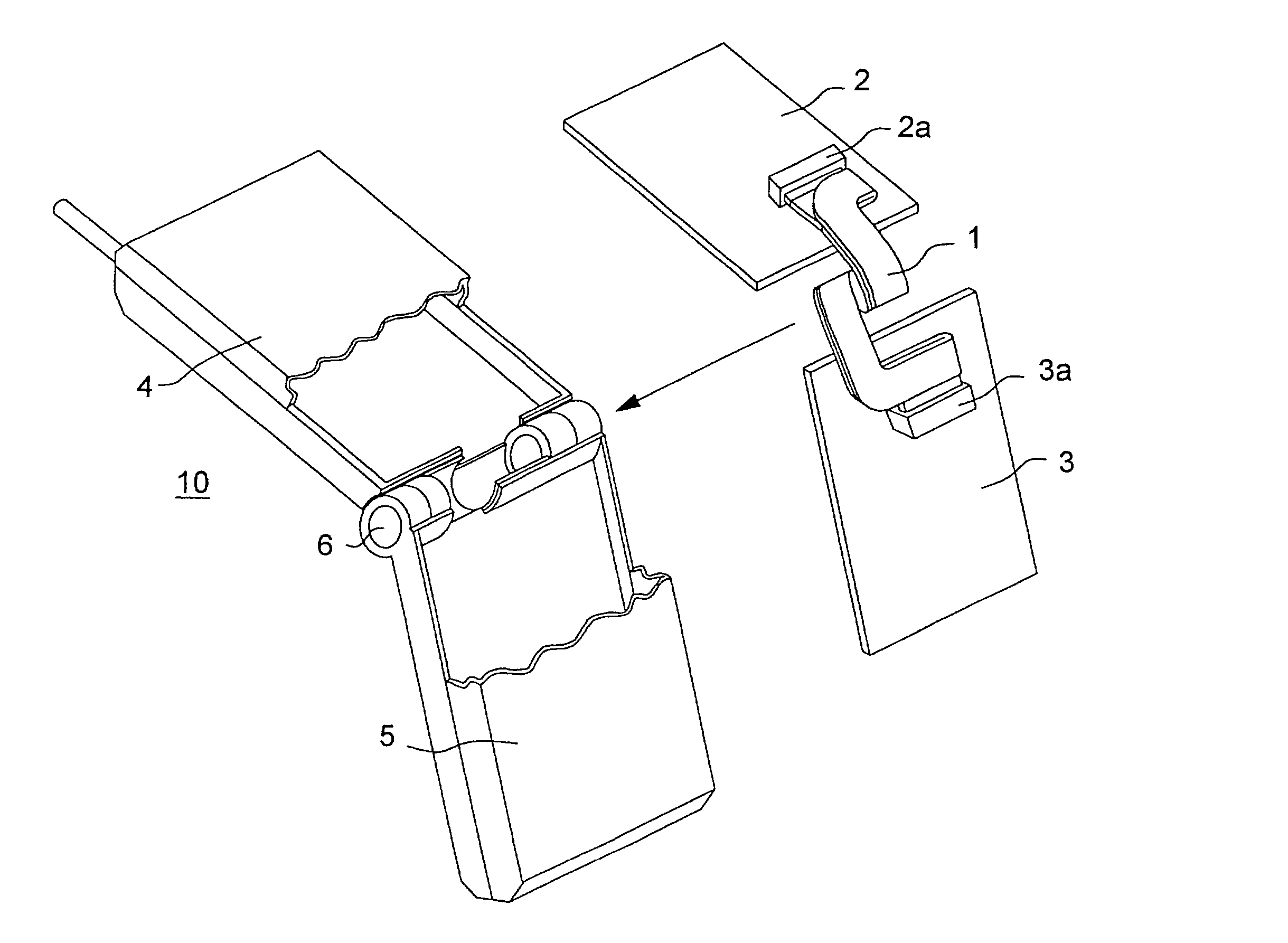
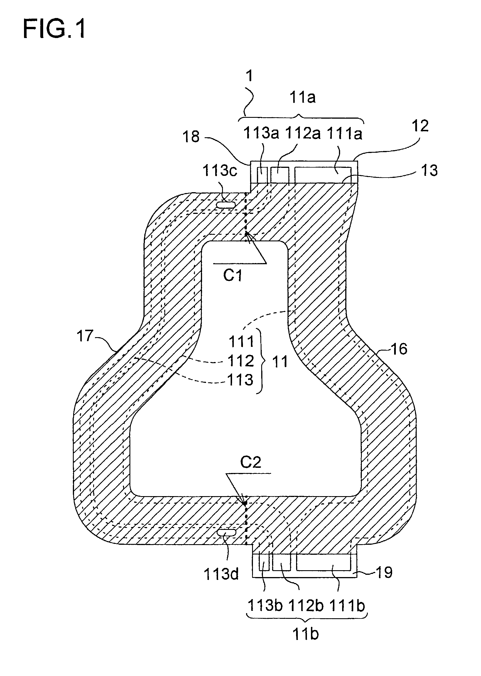
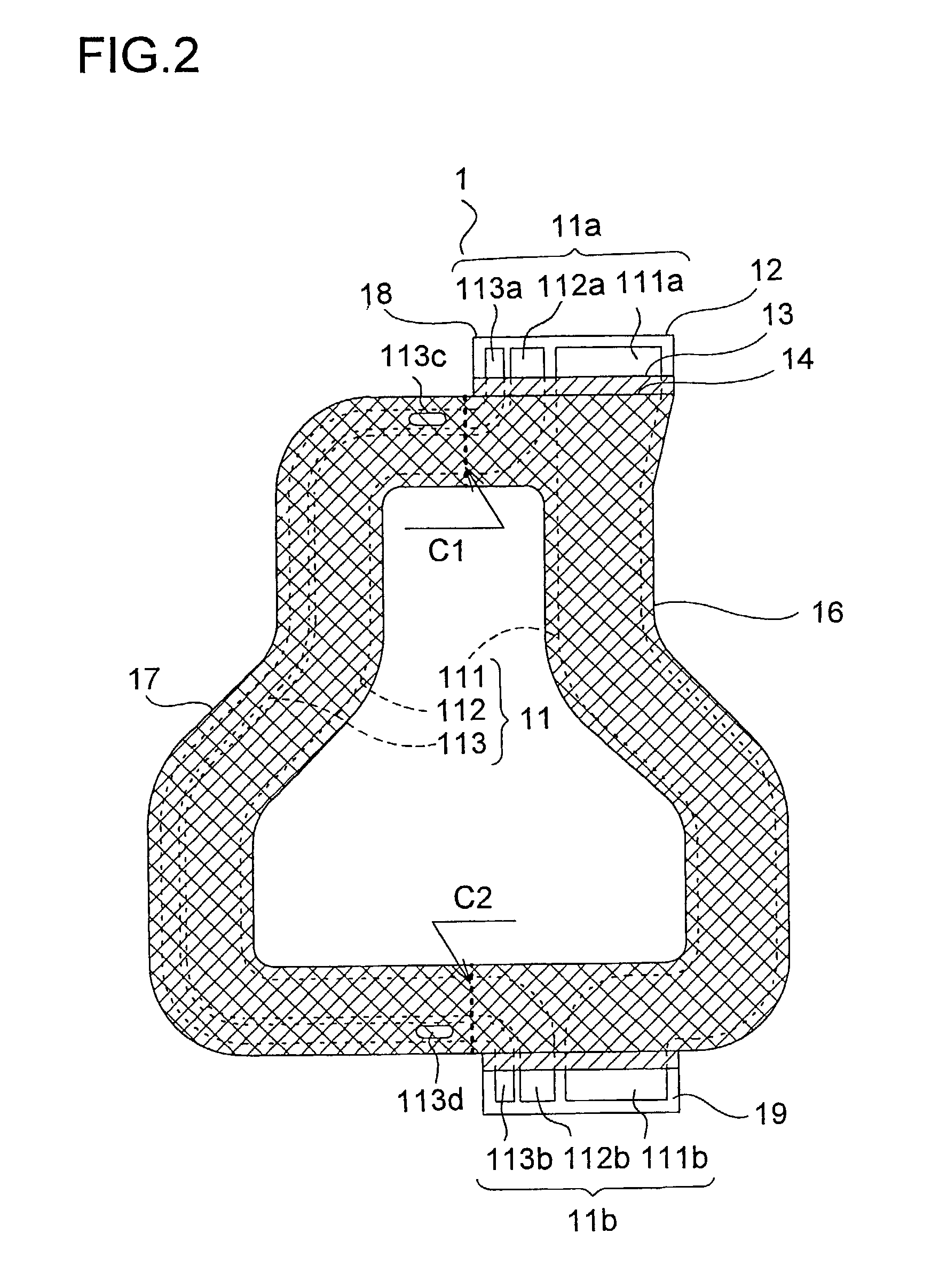
[0018]Hereinafter, an embodiment of the present invention will be described with reference to the drawings. FIGS. 1 and 2 are plan views of a flexible printed circuit board embodying the invention, respectively before and after being shielded. As will be described in detail later, the flexible printed circuit board of this embodiment is incorporated in a folding-type cellular telephone terminal (see FIG. 7),.

[0019]The flexible printed circuit board 1 has a first and a second connection portion 18 and 19 where contact portions 11a and 11b of conductor patterns 11 are exposed. The conductor patterns 11 include a first and a second pattern 111 and 112 for signal transmission and a third pattern 113 for grounding. The first and second connection portions 18 and 19 are connected together by a first path portion 16 where the first pattern 111 is arranged and a second path potion 17 that branches off the first path portion 18 and where the second and third patterns 111 and 112 are arranged...


PUM


Abstract

A flexible printed circuit board has first and second connection portions 18 and 19 where contacts are exposed and first and second path portions 16 and 17 where conductor patterns 11 are arranged that connect the contacts 11a and 11b of the first and second connection portions 18 and 19 together. The first and second path portions 16 and 17 are formed so as to have substantially symmetrical shapes with each other about a predetermined straight line, and the flexible printed circuit board is folded up along the straight line C1 and C2. Alternatively, a flexible printed circuit board has a conductor pattern 11 formed between first and second insulating sheets 12 and 13, and has a shielding conductor 14 fixed to the second insulating sheet 13. The flexible printed circuit board is folded up with the second insulating sheet 13 outside so that the conductor pattern 11 is enclosed inside the shielding conductor 14.

Description

TECHNICAL FIELD[0001]The present invention relates to a flexible printed circuit board of which a portion is bent, and relates also to a folding-type cellular telephone terminal having a flexible printed circuit board of which a portion is bent.BACKGROUND ART[0002]A folding-type (collapsible) cellular telephone terminal, such as a folding-type cellular phone or a folding-type PHS (personal handyphone system) phone, has two body casings coupled together with a hinge portion. Printed circuit boards having electronic components mounted thereon are housed inside the individual body casings, and are connected together with a flexible printed circuit board. To make the folding-type cellular telephone terminal compact, the flexible printed circuit board is required to have a sufficiently small width. Moreover, as disclosed in Japanese Patent Application Laid-Open No. H1-89845, to prevent damage, such as breakage of conductors, resulting from the folding and unfolding of the body casings, t...

Claims


Application Information

Patent Timeline
IPC IPC(8): H04B15/00H04B7/005H04B7/01H04B7/015H04M1/02H04M1/725H05K1/00H05K1/02H05K9/00
CPCH04M1/0216H05K1/028H04M1/725H05K2201/2027H05K2201/055H05K1/0218
Inventor UEYAMA, TOMOKIOSAKI, JIRO
Owner PANASONIC INTELLECTUAL PROPERTY CORP OF AMERICA
Learn More