Method and device for transmitting information on a bus system, and a bus system in which different information is uniquely assigned different information identifiers

a bus system and information technology, applied in the field of bus systems, can solve the problems of high bus load, inability to provide optimal, and inability of related art, in particular the lin bus, to signal a local event to the master, etc., to reduce the reaction time of the lin bus, improve the bus performance, and reduce the effect of the reaction tim

Inactive Publication Date: 2006-01-24
ROBERT BOSCH GMBH
View PDF4 Cites 112 Cited by
  • Summary
  • Abstract
  • Description
  • Claims
  • Application Information

AI Technical Summary

Benefits of technology

[0011]This expansion, for example of the existing LIN specification, may reduce the reaction times on the LIN bus.
[0012]Thus, the slaves or subordinate users in a master / slave bus system may signal local events by themselves. The slaves may then accordingly be specifically queried by the master, and they may not have to be sequentially polled. In this manner, local events at the slaves may be detected more rapidly, which may substantially improve bus performance in existing platform configurations such as a DPM design (distribution power module), or with keyless entry.
[0013]On the LIN bus, for example, the reaction times may thereby shortened, and the additional bandwidth may offer additional applications to use the cost advantages of a simply structured bus system, such as a LIN bus system.

Problems solved by technology

The LIN slaves in this method may not signal a local event to the master.
Consequently, depending on the application and data volume, this may result in a high bus load, even with few time-critical signals, due to the time-intensive polling of the slaves, i.e., the time-intensive ascertainment of readiness for receiving or sending.
Thus, it may be shown that the related art, in particular the LIN bus, may not be capable in every respect of supplying optimal results.

Method used


Image

  • Method and device for transmitting information on a bus system, and a bus system in which different information is uniquely assigned different information identifiers
  • Method and device for transmitting information on a bus system, and a bus system in which different information is uniquely assigned different information identifiers
  • Method and device for transmitting information on a bus system, and a bus system in which different information is uniquely assigned different information identifiers

Examples


Embodiment Construction

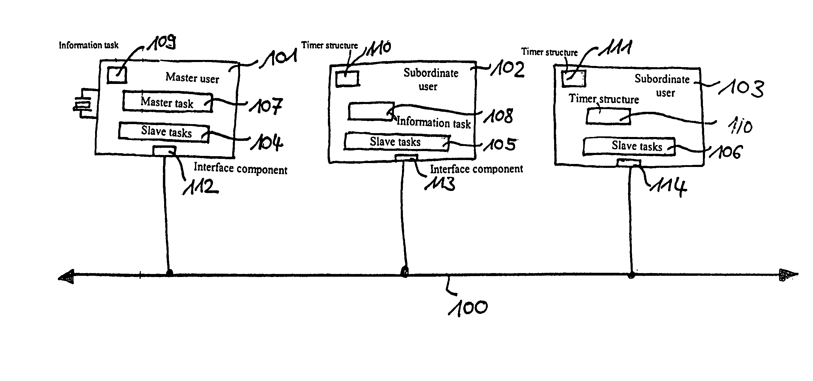
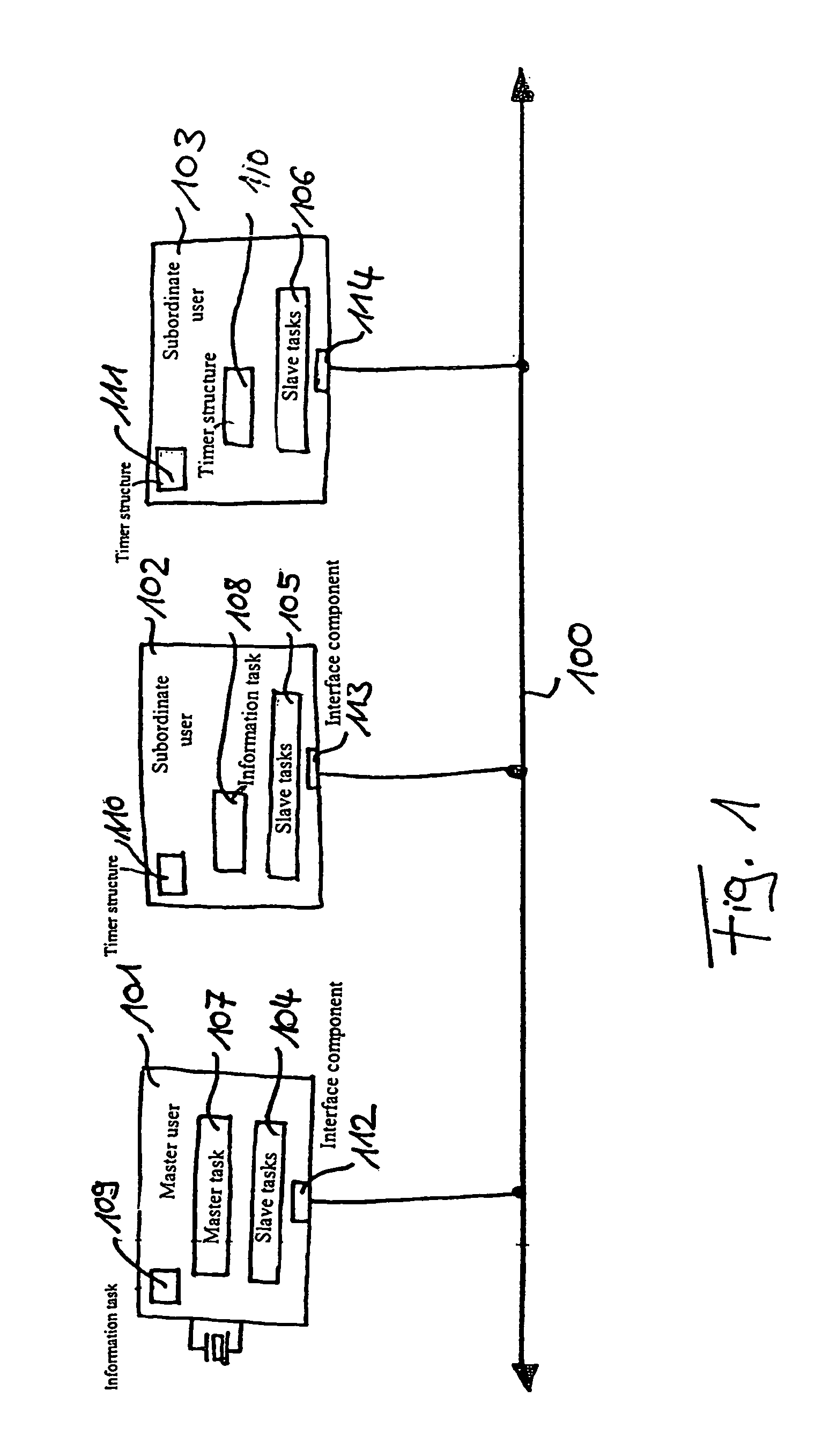
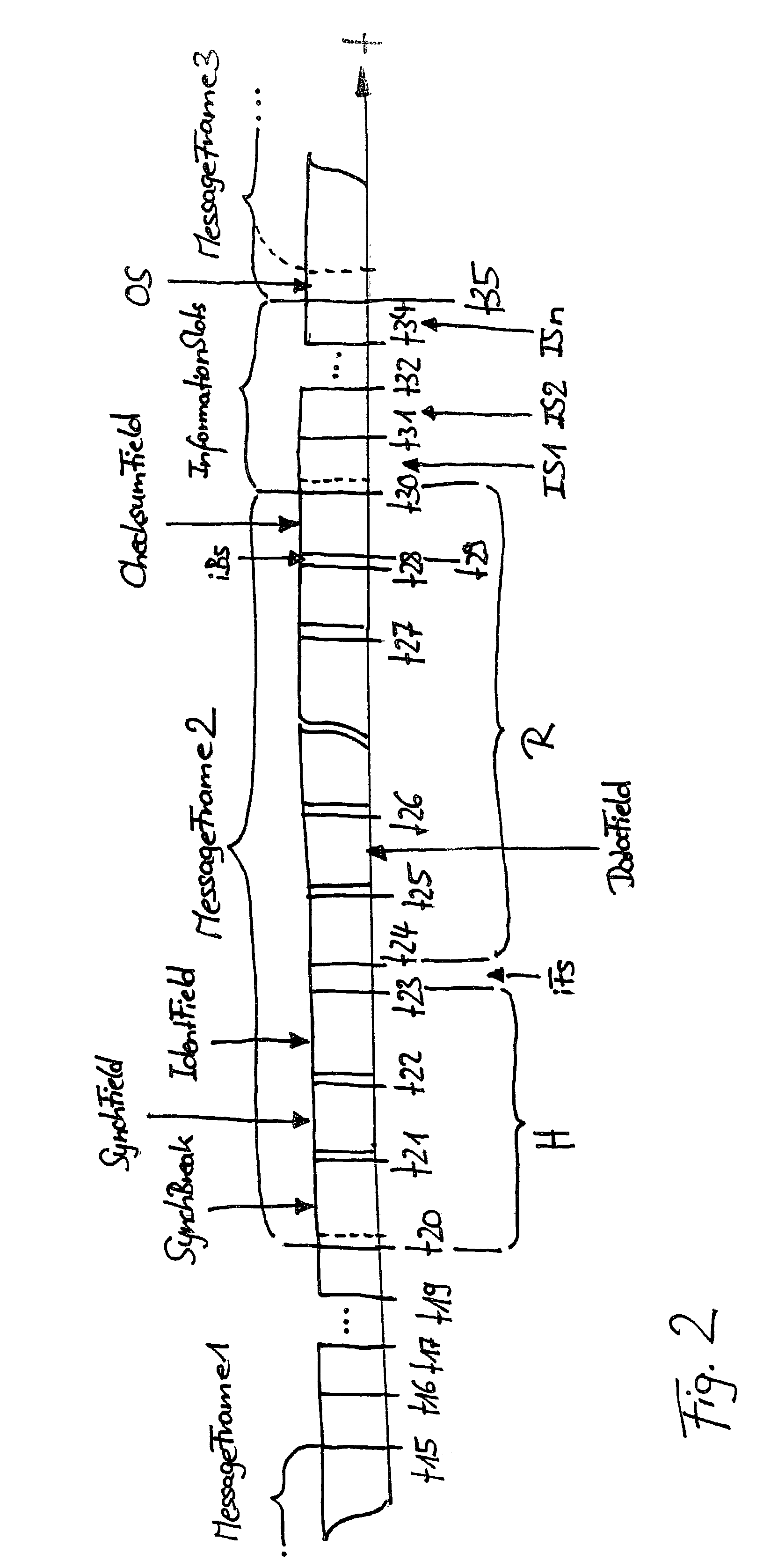
[0018]FIG. 1 shows a bus system according to the present invention, specifically a LIN bus system having bus users 101 to 103. These users 101 to 103 are connected to each other via bus line or bus 100. In this context, a superordinate user, or master, is depicted as user 101 in the bus system. Users 102 and 103 represent subordinate users or slaves. As previously mentioned in the background description, the LIN protocol divides the transmission and reception process into two tasks. The master task or header H contains the synchronization and addressing via the fields SynchBreak, SynchField and IdentField, and the slave task or response R includes the data or data field and the checksum field.

[0019]In FIG. 1, the slave tasks or the arrangement of the particular bus users 101 to 103 executing them are depicted as 104 to 106. Likewise, the master task, or the arrangement executing it, is represented by block 107, which, for example, may not prevent the same arrangement from executing ...


PUM


Abstract

A method and device is described for transmitting information on a bus system having at least two users, as well as a bus system, exactly one superordinate user (master) and at least one subordinate user (slave) being provided, and the information being transmitted in a definable, closed message frame which, in addition to the information to be transmitted, also contains synchronization information, different information being uniquely assigned different information identifiers; after each closed message frame, a number of information sections being provided in which the at least one subordinate user may enter information.

Description

FIELD OF THE INVENTION[0001]The present invention relates to a method and a device for transmitting information on a bus system, and a bus system that has at least two users, exactly one superordinate user (a so-called master) and at least one subordinate user (a so-called slave).BACKGROUND INFORMATION[0002]The networking of control units, sensors and actuators with the aid of a communication system, that is, a bus system, has increased in recent years in the construction of modern motor vehicles and in machine construction, for example in the field of machine tools and in automation. In this context, synergy effects due to the distribution of functions to several control units or other users may be achieved. These are referred to as distributed systems. The communication between different users of such distributed systems may occur more and more via a bus or a bus system. The communication traffic on the bus system, access and reception mechanisms, as well as error recoveries may b...

Claims


Application Information

Patent Timeline
Patent Type & Authority Patents(United States)
IPC IPC(8): G06F13/38H04J3/24H04J3/06H04L12/40H04L12/413
CPCH04L12/40156H04L12/403H04L2012/40234
Inventor DALAKURAS, LAMBROSBOEHM, ANDREAS
Owner ROBERT BOSCH GMBH
Why Eureka
Try Eureka