Flexible reflective skylight tubes

a skylight tube and flexible technology, applied in the field of skylights, can solve the problems of light absorption, off alignment of skylight opening and ceiling opening, and light limitation in townhouses or row houses in particular

Inactive Publication Date: 2006-01-31
WESTON GARY
View PDF17 Cites 14 Cited by
  • Summary
  • Abstract
  • Description
  • Claims
  • Application Information

AI Technical Summary

Benefits of technology

[0008]The present invention relates to a light and air conducting tube which connects between a skylight and a ceiling opening through an attic or like space between the roof and the ceiling of a house. The light and air conducting tube is somewhat flexible to allow bending of the tube to match the locations of a skylight and a ceiling opening should they not be aligned. At the same time the tube is firm enough to not collapse under its own weight. The inner surface of the light and air conducting tube has a highly reflective tube for greater light transmission. To further increase the amount of light transmitted, the tube has a square or rectangular cross-section, which increases the area approximately 27% more than a circle.
[0009]The construction of the light and air tube includes a reflective liner of a suitable plastic, a center insulation, such as bubble wrap, and an outer liner of aluminum foil. This construction provides good light transmission, insulation against cold and heat, and a good fire retardant radiant barrier.
[0010]The skylight has a dome covering the top opening, such dome is preferably white to further maximize the light transmitted to the interior of the building.
[0011]It is therefore and object of the present invention to provide a new and improved roof to ceiling skylight which may be easily manufactured as a reasonable cost.
[0012]Another object of the present invention is to provide a skylight assembly that has the flexibility to bend and conform in an attic space to align with both a skylight and a ceiling opening.
[0014]Still a further object of the present invention is to provide a new and improved roof to ceiling skylight apparatus which eliminates the need for a customized construction of a light conveyance between a roof-mounted skylight and a ceiling-mounted translucent fixture.

Problems solved by technology

Townhouses or row houses in particular are faced with light limitations, except for end units, they only receive sun light from two directions.
The problem is that the sunlight reflects off the shaft, which has been painted, some of the light is absorbed, particularly when the angle of the sunlight is low.
Another problem is when a skylight and shaft are added after a house is built, the alignment of a skylight opening and a ceiling opening may be off.

Method used


Image

  • Flexible reflective skylight tubes
  • Flexible reflective skylight tubes

Examples


Embodiment Construction

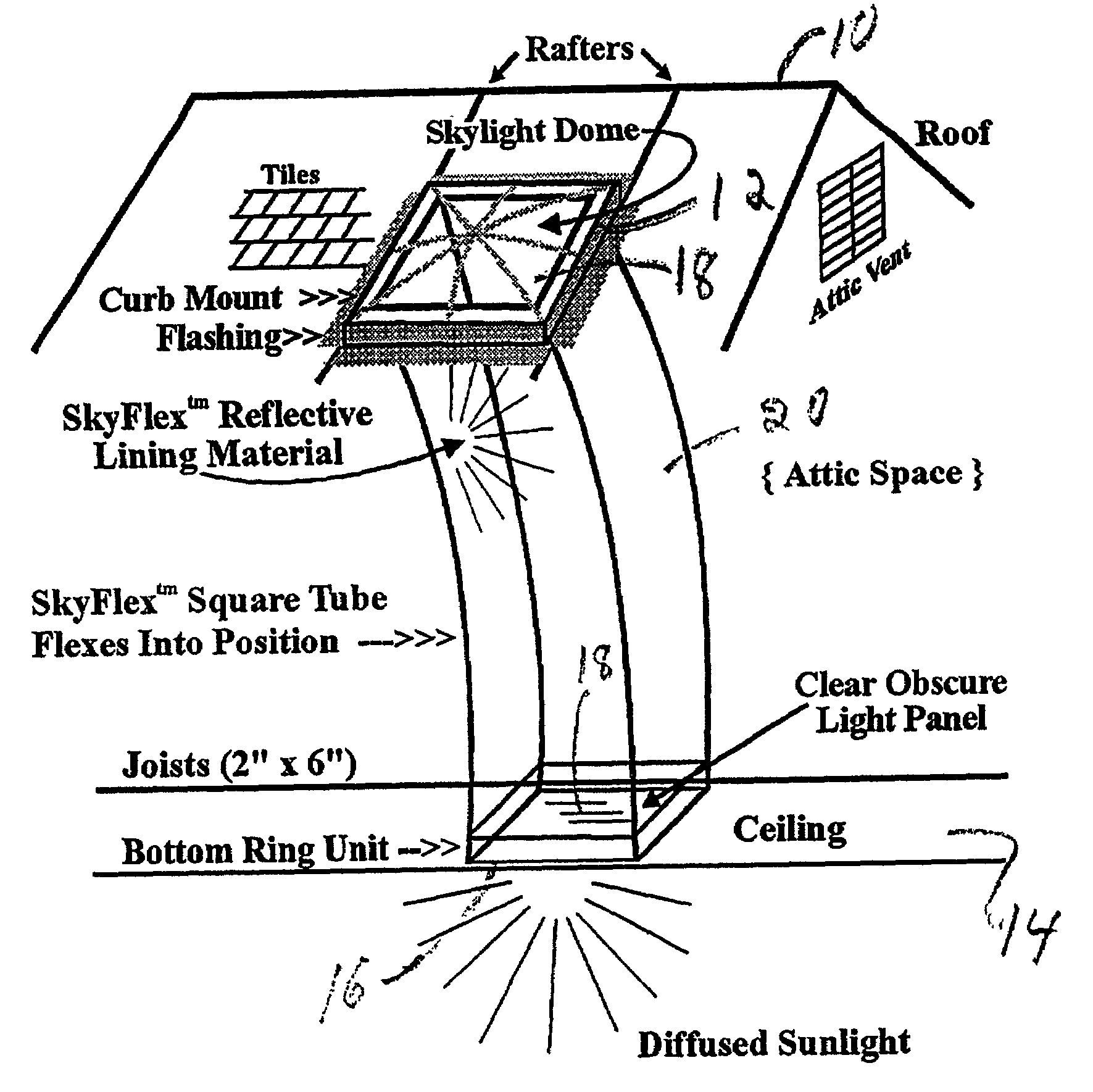
[0018]Referring to the drawings, FIGS. 1 to 3, there is shown the outline of a house or building roof 10, having a skylight 12, and a partial section of an interior ceiling 14 having an opening 16 covered by a light panel 18, a light and air conducting tube 20 connects the skylight 12 to the ceiling light panel 18. As can be seen, the skylight 12 and the ceiling light panel 18 are out of alignment. That is to say, they are not in vertical alignment therefore, the light and air conducting tube 20 is flexible in order to connect skylight 12 to ceiling light panel 18. While the tube 20 is flexible, it is still firm enough to support its own weight.

[0019]It is shown in FIG. 1, that the light and air conducting tube has a square or rectangular cross-section which among other things provides a larger light area than would a round or circular cross-section.

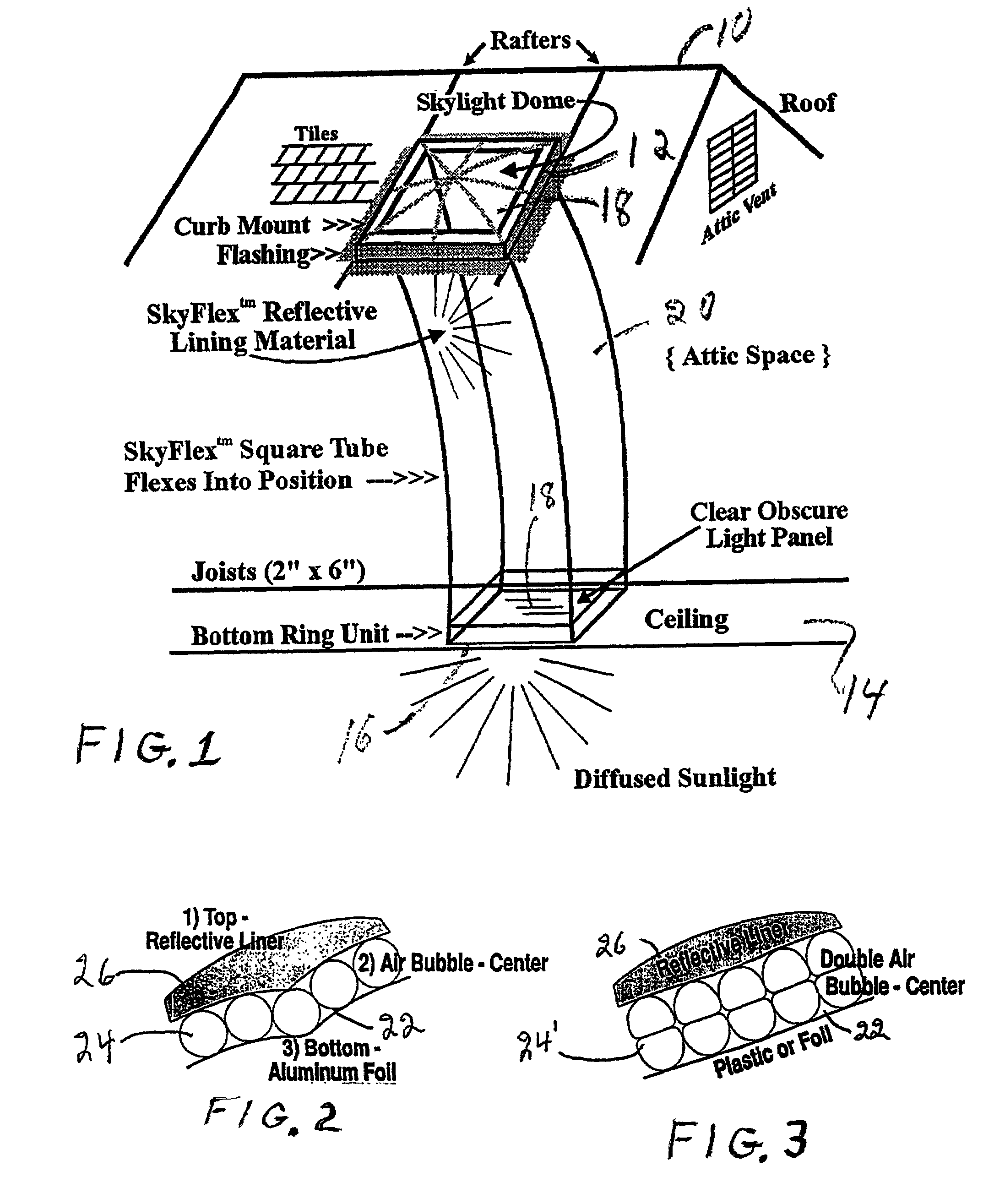
[0020]FIG. 2 shows a partial cross-section of a light and air conducting tube 20. Having an interior liner 22, a center insulation core...


PUM


Abstract

This invention relates to a flexible light conduit having two ends, one end mounted to an outdoor support such as a roof and at it's other end to a ceiling or other support inside a structure such as a house, garage, shed or other structure, said light conduit being of any shape in cross section, preferably square or rectangular and lined with any material or combination of materials for insulation, ornamentation and the like.

Description

BACKGROUND OF THE INVENTION[0001]The present invention relates to skylights and, more particularly, to a skylight system with a tubular light conduit connecting to a roof skylight device to a ceiling skylight device.[0002]Roof skylights are a means to provide daylight into a room with limited amounts of available daylight. Usually, such rooms have no windows or one window. Townhouses or row houses in particular are faced with light limitations, except for end units, they only receive sun light from two directions. As the earth rotates about the sun and depending on which direction a house faces, a room may receive a lot or a little sunlight. To overcome the limited available sunlight coming into a room, skylights were invented.[0003]The early skylights had metal frames and glass panes with wire mesh embedded in the panes for safety purposes. The skylight was mounted on a roof over a shaft leading from the roof to a ceiling. Generally, the shaft was covered with wood or plaster board...

Claims


Application Information

Patent Timeline
IPC IPC(8): E04B7/18E04D13/03
CPCE04D13/03E04D2013/0345
Inventor BORGES, MICHAEL
Owner WESTON GARY
Why Eureka
Try Eureka