Narrow aerial and die-mount cams

a technology of die-mounted cams and aerials, which is applied in the direction of forging presses, forging/pressing/hammering apparatus, shaping tools, etc., can solve the problems of increased cam width, increased cams, and increased cams from their presses to replace worn parts, so as to reduce costs and facilitate assembly and installation.

Inactive Publication Date: 2006-01-31
ANCHOR LAMINA AMERICA INC
View PDF11 Cites 32 Cited by
  • Summary
  • Abstract
  • Description
  • Claims
  • Application Information

AI Technical Summary

Benefits of technology

[0020]The aerial and die-mount cams are basically inverted versions of each other. Efficiencies of assembly and installation and reduced expenses can be realized by using cam adapters, slides and drivers that have components that do not require custom fitting. The self-lubricating material on one of each pair of bearing and contacting surfaces extend the life of contacting surfaces that slide relative to one another.

Problems solved by technology

Previous attempts to increase load-bearing capacity have included broadening bearing surfaces, but these have increased the width of the cams.
Having to remove cams from their presses to replace worn parts can be a costly and time-consuming activity.
Fasteners such as bolts that hold parts together are more likely to loosen or fail if they are placed under stress during press operation.
Their design and construction result in additional expenses.

Method used


Image

  • Narrow aerial and die-mount cams
  • Narrow aerial and die-mount cams
  • Narrow aerial and die-mount cams

Examples


Embodiment Construction

)

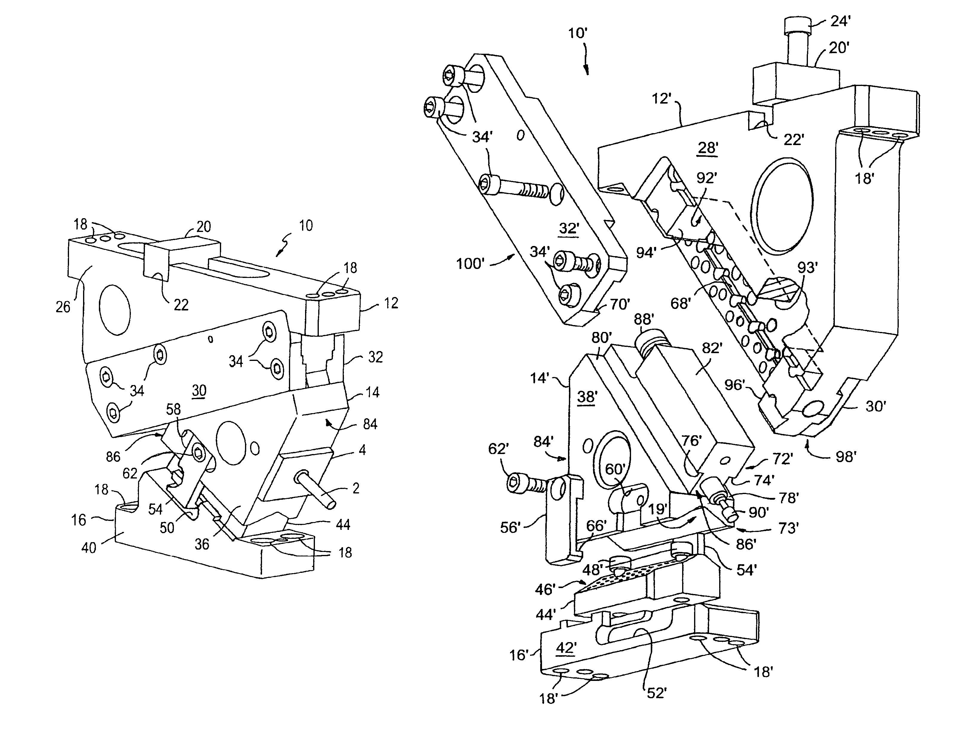
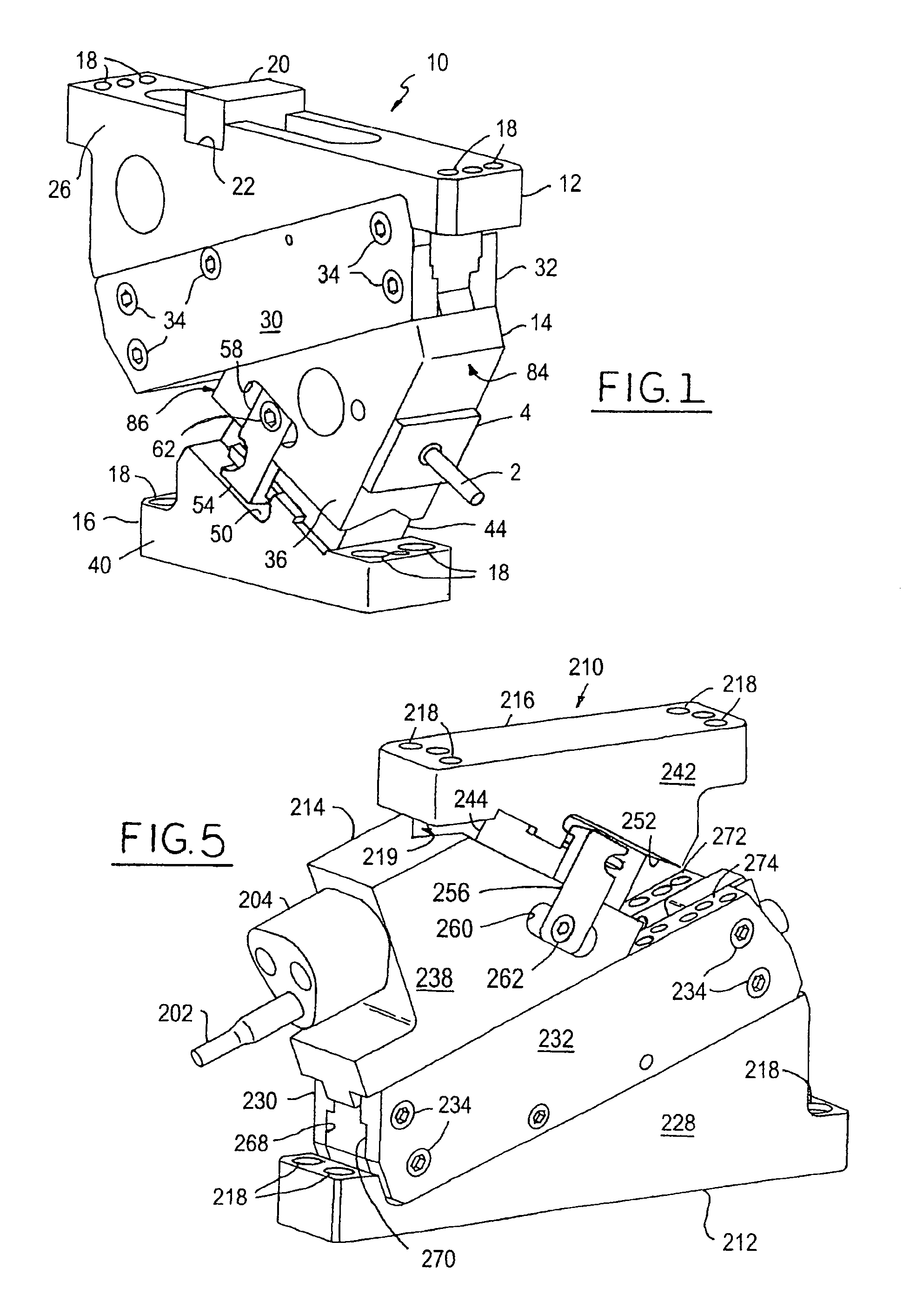
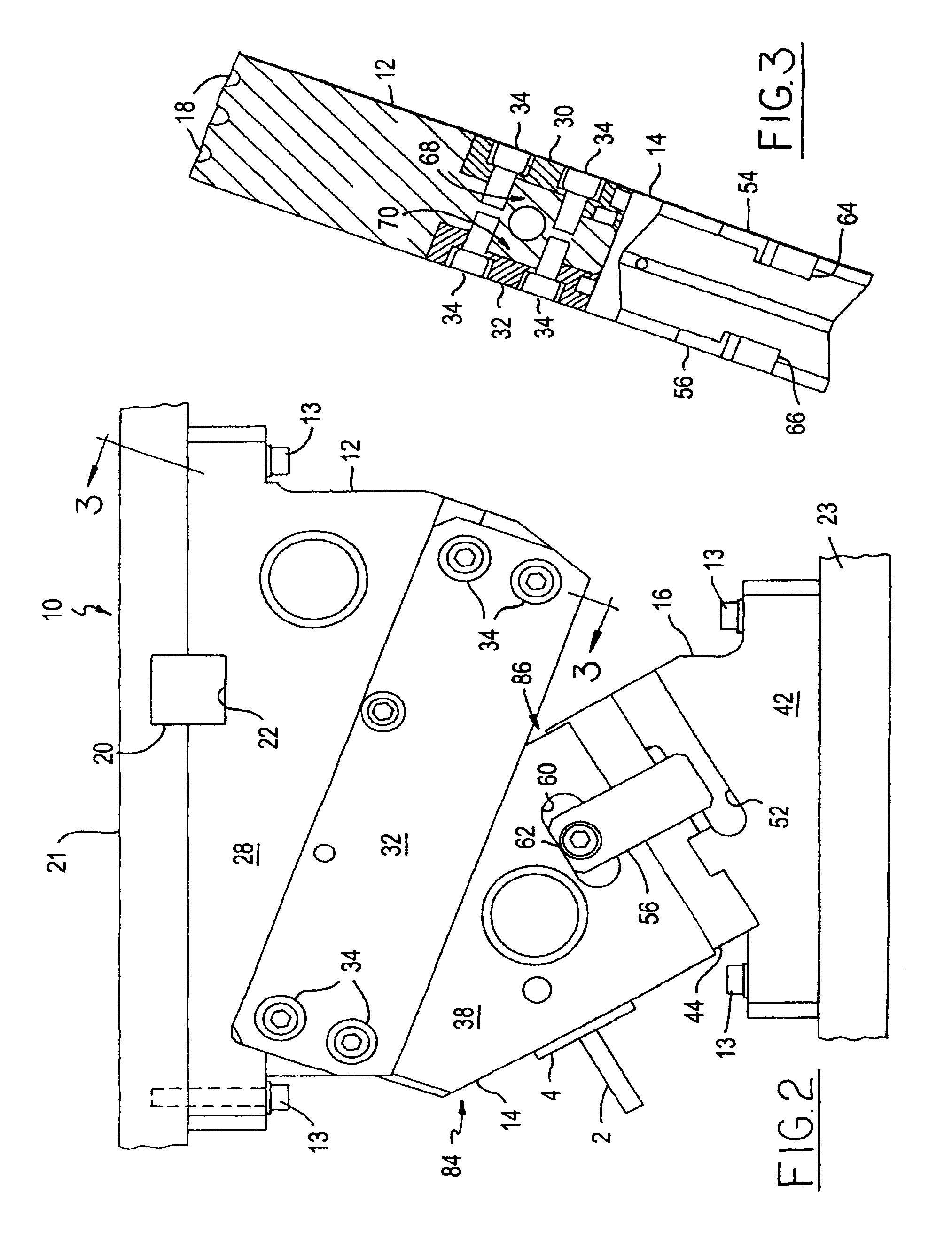
[0026]It should be noted that, when the term “cam” is used in this specification without particular reference to the type of cam, the term refers inclusively to aerial cams and die-mount cams. It should be further noted that FIGS. 1, 2, 3 and 5 do not show inner details of the cams. FIG. 4, however, is an exploded view that does reveal details of the inner structures. FIGS. 4 and 5 show only one side of each cam represented, but the respective opposite sides and the components and features located there are mirror images of the components and features located on the sides shown.

[0027]FIG. 1 is a perspective view of a front and first side of a representative narrow aerial cam, generally indicated by the reference numeral 10, that includes a cam driving member, or cam adapter, 12, a tool holding member, or slide, 14, and a driver 16. The cam adapter 12 is secured, typically by bolts 13 (FIG. 2) passing through bolt holes 18, to an upper platen 21 (FIG. 2) of a press (not shown). To f...


PUM

PropertyMeasurementUnit
widthaaaaaaaaaa
distanceaaaaaaaaaa
resilientaaaaaaaaaa

Abstract

Narrow aerial and die-mount cams, each having a cam adapter, a driver and a slide sandwiched between the cam adapter and driver. The narrow aerial cam slide has an elongate primary portion that has a T-shaped cross-section and has a primary bearing surface, and the cam adapter has a rectangular recess. An elongate keeper plate having a longitudinal slot is secured to each side of the cam adapter adjacent the rectangular recess to slidably retain the primary portion of the slide within the longitudinal slots and the rectangular recess. The primary bearing surface and a pair of intermediate bearing surfaces formed in the slide below the primary portion slidably support the keeper plates and thus the cam adapter. The driver slidably supports the slide. The narrow die-mount cam is basically an inverted version of the aerial cam.

Description

BACKGROUND OF THE INVENTION[0001]1. Field of the Invention[0002]The invention relates generally to aerial and die-mount cams and more particularly to improvements in cams configured to provide an increased load-bearing capacity and to facilitate the fabrication of long-lived, narrow cams having components that do not require custom fitting.[0003]2. Background Art[0004]Aerial and die-mount cams are often used to operate tools for such manufacturing processes as punching, trimming, stamping and bending workpieces. These devices include elements that convert downward and upward forces provided by a press into laterally directed component forces that advance and retract a tool in lateral directions to effect the mentioned processes.[0005]Since some manufacturing processes require the application of considerable forces, an important feature of cams is their load-bearing capacity. Cams in present use typically have a maximum load-bearing capacity of some 1.5 tons. Previous attempts to inc...

Claims


Application Information

Patent Timeline
Patent Type & Authority Patents(United States)
IPC IPC(8): B21D5/04B26D5/16
CPCB21D37/08B21D28/32Y10T83/8831Y10T83/8853
Inventor FIDZIUKIEWICZ, ERICH D.
Owner ANCHOR LAMINA AMERICA INC
Why Eureka
Try Eureka