
Pendulum impact test rig

a test rig and impact technology, applied in the field of crash testing rigs, can solve the problems of inability to accurately assess the crashworthiness of vehicle components such as motorcycles or automobile wheels, high cost and space consumption, and limited working space, so as to reduce the weight of the arm, improve the control feature of the center of percussion, and increase the impact energy

Inactive Publication Date: 2006-01-31
UNIVERSITI PUTRA MALAYSIA
View PDF4 Cites 27 Cited by
  • Summary
  • Abstract
  • Description
  • Claims
  • Application Information

AI Technical Summary

Benefits of technology

[0019](5) The center of percussion of the pendulum needs to be as close as possible to the impact line, in order to minimize the impulsive reaction that may cause the deformation and bending of the arm, and eventually the whole system.
[0023]According to the present invention, the most important feature of the pendulum test rig is that it allows for controllable center of percussion in the impact region while allow for varying the striking weight and varying the locations of striker along the lower end portion of the pendulum arm. The present pendulum test rig is found to have a better controlling feature of center of percussion of the pendulum compared to that developed for SAE J1981 standard. With equivalent arrangement, the percentage of deviation of center of percussion from midpoint of striker's striking edge is found to be about 14% for the pendulum developed for SAE J1981 but is about only 7% for the present developed pendulum. A structural T-beam is selected as pendulum arm instead of other types of structural beam in the present invention for several reasons. Firstly is that the T-beam reduces a weight of the arm to a large extent compared to other types of beam such as square type and I-beam for equivalent length. This is helpful for controlling the center of percussion in the lower end portion of the arm, where the striker is usually located or the impact always occurs. Secondly is that the space behind the flange and at both sides of the web provides a suitable place to locate the fixed masses and a series of additional masses, where the web is used to secure these masses whereas the flange gives a front support when the pendulum swing and impact the test specimen. The fixed masses assist to locate the center of percussion in the striking region. The series of additional masses varies the striking weights that can be applied and to generate a higher impact energy. In a preferred embodiment, the pendulum arm is constructed in such a way that it can be raised to about 170° from free hanging position in order to optimized its capacity
[0024]In a preferred embodiment, a striker is releasably, rather than permanently, secured to the arm. This is to facilitate the removal of the striker for replacement when damage, for shifting to a lower or higher location along the end portion of the arm for impacting with test item at different location, and for exchanging different designs of striker to better simulate the impact conditions experienced by the test body resulted from different striking object with different geometry of contact surface.

Problems solved by technology

Actual full-scale crash tests to assess crashworthiness of vehicle components such as motorcycle or automobile wheels is expensive and space consuming since they require the use of sleds or moving barriers to simulate the impact.
This is particularly inappropriate and unworthy when only a specific critical component of a vehicle is to be investigated, under varying impact conditions and great number of test parameters.
Among the shortcomings of such test system are expensive and may not suit the requirement of testing, the working space may be limited to a small test specimen.
The major drawback of in-house fabrication is that expertise is highly needed in mechanical and electronic installation and commissioning to ensure a reliable performance.
Free-fall carriages have to be guided and thus the friction can vary not only due to binding during the actual free fall but also due to more severe binding after the striker hits the test item and creates some offset loading.
The free fall test rig requires expensive and rigid guidance equipment if binding is to be kept to a minimum.
In terms of maintenance, a pendulum with just two self-aligning bearings is easy to maintain whereas free fall equipment with its guides and linear bearings is difficult to maintain.
One of the disadvantages of this test rig is its relatively high deviation of center of percussion from the striker nose, or the impact region.
Difficulties that would occur with this are:(1) Shock will be transmitted back to the supporting frame, and this would causes erroneous readings of the impact value.(2) The pendulum will be more susceptible to damage by bending or by fracture.(3) The pendulum will absorb high deformation energy causing erroneous impact readings.(4) The bearings will deteriorate rapidly.
Another disadvantage is that the test rig does not provide flexibility for varying the striking weight.
The problem with this is it creates a laterally instability when the pendulum swings, which will cause a connection failure at pivot point and deteriorate the bearings that support the shaft.
Also, it creates a significant moment at the extended portion that oppose to the striking moment which will reduce the effective velocity, force, and energy delivered.

Method used


Image

  • Pendulum impact test rig
  • Pendulum impact test rig
  • Pendulum impact test rig

Examples


Embodiment Construction

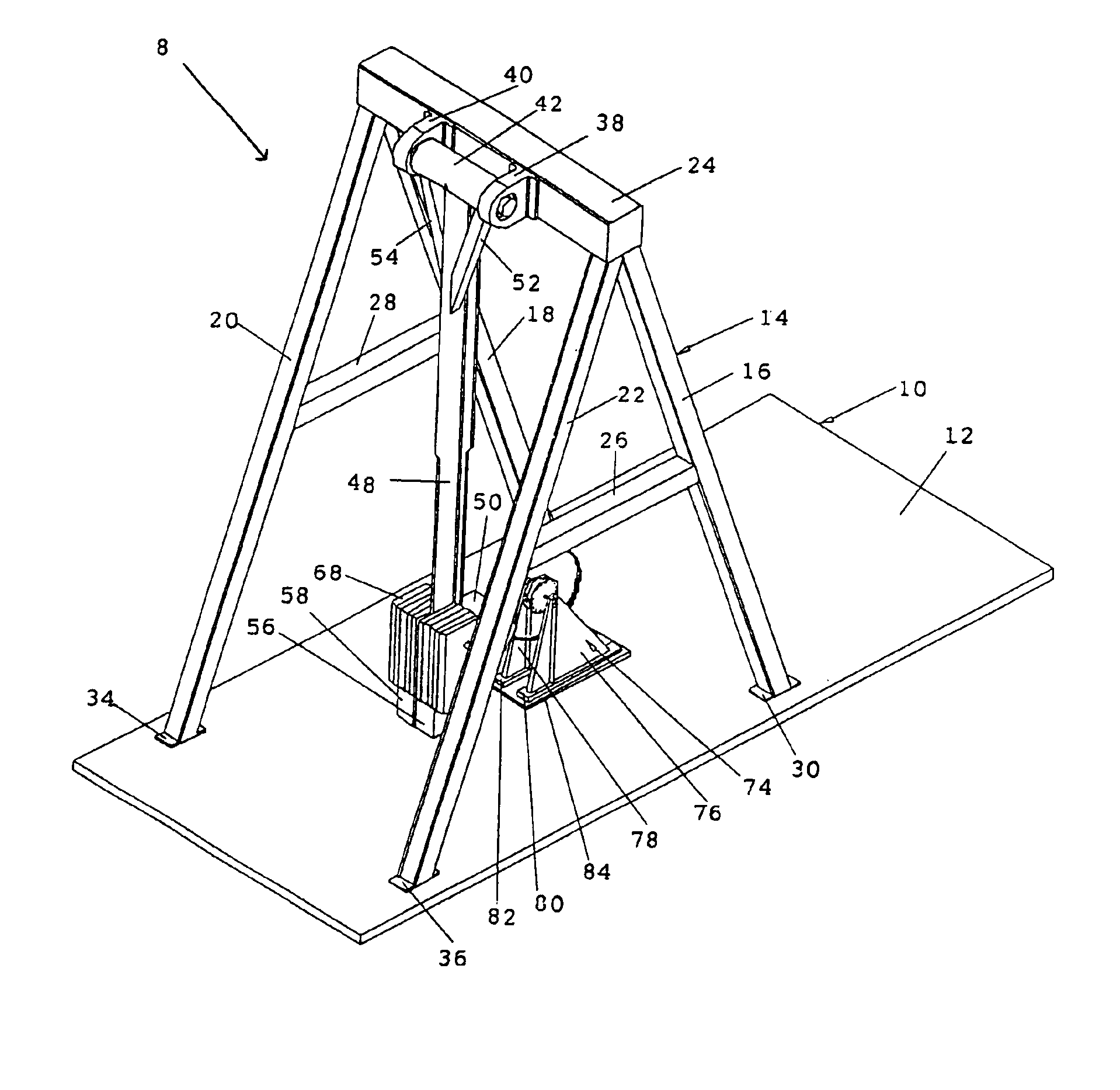
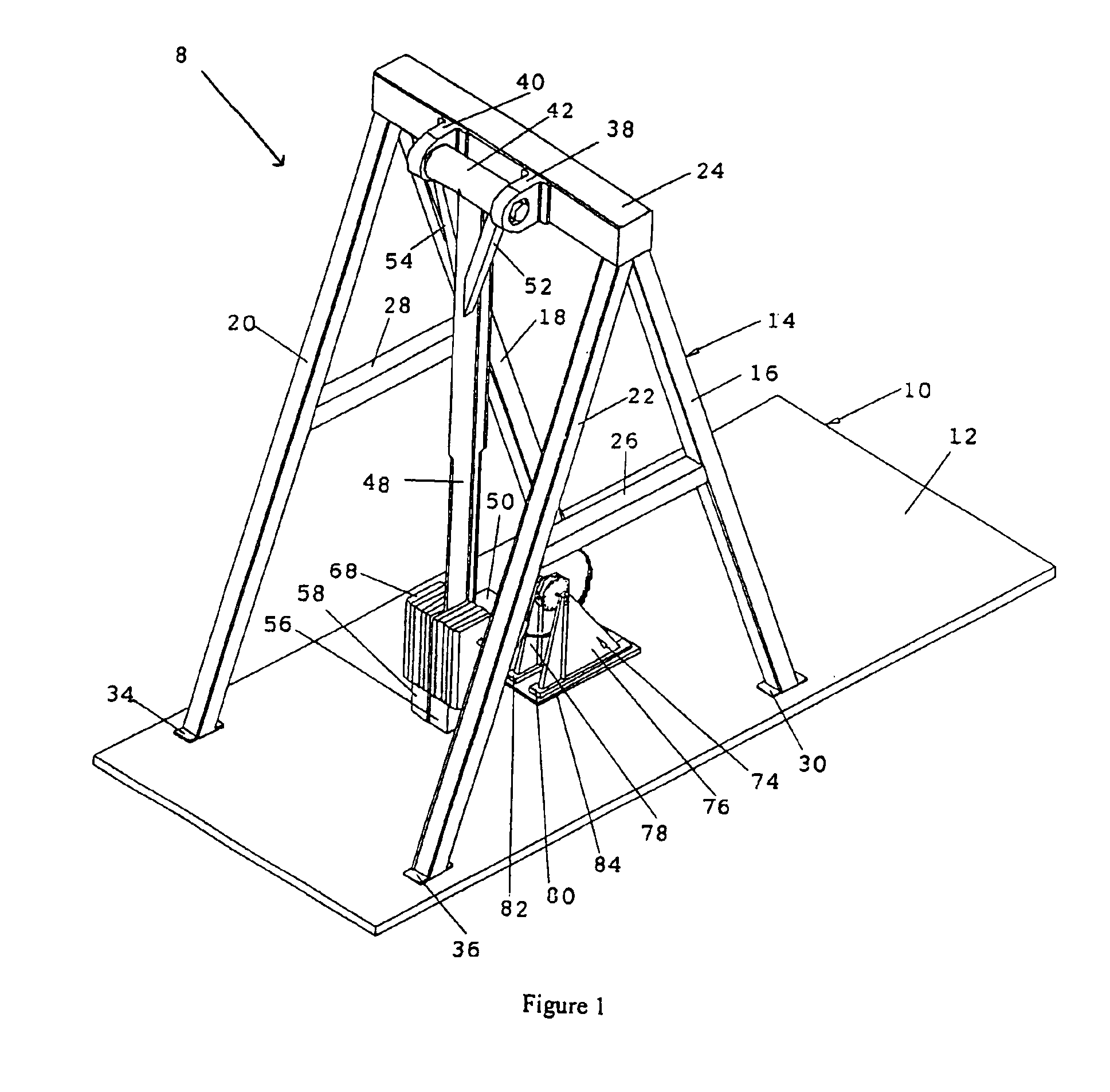
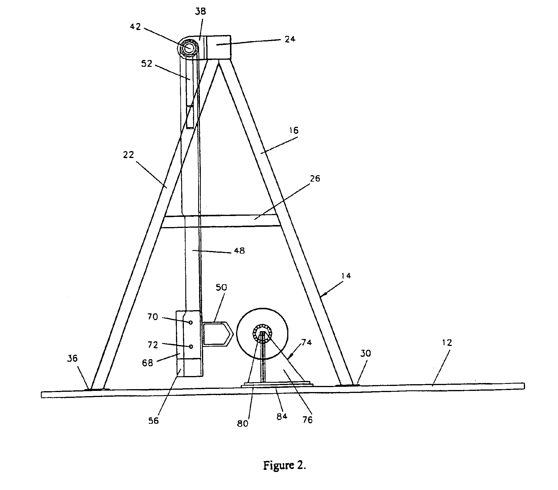
[0035]FIGS. 1 to 3 illustrates a pendulum impact test rig (8) according to the preferred embodiment of the present invention for crash testing the structural components. The test rig (8) is generally comprises of base portion (10) and pendulum supporting frame (14) positioned thereon.

[0036]In a preferred embodiment, base portion (10) is generally a thick plate member (12), which is preferably secured to a suitable supporting surface such as a concrete floor or the like by any convenient means such as bolts. The pendulum supporting frame (14) is a pair of “A” structure supporting frames, constituted of four inclined upstanding structural frame members (16, 18, 20, 22), one horizontal main frame member (24) secured to the vertex of the upstanding structural frame members (16, 18, 20, 22) and another two horizontal structural frame members (26, 28) which are secured to and extend between the frame members (16, 22) and (18, 20) respectively for extra support. At the bottom of the upstan...


PUM


Abstract

The pendulum impact test rig is designed and developed for simulating impact conditions experienced by structural components in real-world crash or full-scale crash test. The test rig can be adopted for crash testing individual vehicle component. The test rig comprises of a base plate which is anchored to a concrete ground, a pendulum supporting structure positioned on the base plate, a pendulum member constructed from structural T-beam that permanently secured to a rotatably shaft, and a test item holding device releasably mounted on the base plate. The pendulum member includes a striker which is releasably attached to the lower end portion of the pendulum, fixed masses permanently secured at the lower end portion of the pendulum, and additional masses detachably attached immediately above the fixed masses. With present preferred embodiment, the center of percussion is controlled within the striking zone. Computer-based instrumentation system, which comprises accelerometer, high speed imaging system, light beam emitter-detector velocity measurement, data acquisition card, and computer with data acquisition and analysis application software installed is provided so that the desired data can be acquired for analysis and presentation.

Description

FIELD OF INVENTION[0001]The present invention relates generally to a crash testing rig for structural component, and more specifically to a heavy-duty crash testing rig designed for simulating crash conditions during frontal direct crash for motorcycle frontal components and for impact tests on other vehicle components.BACKGROUND OF THE INVENTION[0002]There is an increasing interest in investigating the dynamic strength and impact characteristics of various vehicle components in the effort to enhance the crashworthiness features of those components. Actual full-scale crash tests to assess crashworthiness of vehicle components such as motorcycle or automobile wheels is expensive and space consuming since they require the use of sleds or moving barriers to simulate the impact. This is particularly inappropriate and unworthy when only a specific critical component of a vehicle is to be investigated, under varying impact conditions and great number of test parameters. In such a case, a ...

Claims


Application Information

Patent Timeline
IPC IPC(8): G01N3/00G01N3/48
CPCG01N3/48G01N2203/0623G01N2203/0087
Inventor VOON, WONG SHAWSOHADI, RADIN UMAR RADINHAMOUDA, ABDEL MAGID S.AHMAD, MEGAT MOHAMAD HAMDEN MEGATSHENG, TAN KEAN
Owner UNIVERSITI PUTRA MALAYSIA
Learn More