Load indicating member with identifying mark

a technology of identifying marks and load indicating members, which is applied in the direction of load modification fasteners, screws, instruments, etc., can solve the problems of not being able to demonstrate the generation of transverse waves using the polymer film transducer disclosed by kibblewhite in u.s. pat. no. 4,846,001, and achieves reliable precise load measurement

Inactive Publication Date: 2006-01-31
INNOVATION PLUS
View PDF24 Cites 52 Cited by
  • Summary
  • Abstract
  • Description
  • Claims
  • Application Information

AI Technical Summary

Benefits of technology

[0012]A primary object of the present invention is to provide a practical method of storing a complete ultrasonic signature for individual high-volume production fasteners in a manner that can be retrieved at a later time by different instrumentation at different locations for reliable precise load measurement for verification of joint integrity.

Problems solved by technology

Historically, however, the practical difficulties in achieving reliable acoustic coupling and in incorporating transducers in tool drives have prevented this technique from becoming a general assembly tightening strategy.
Although the invention represented a significant advance over the prior state of the art in terms of performance, ease of manufacture, and manufacturing cost, there are disadvantages with a transducer of this construction.
These disadvantages relate to environmental performance, in particular the maximum temperature limitations of the polymer material which restricts its application, and the possibility of the transducer, fixed to the fastener with adhesive, coming loose and causing an obstruction in, or damage to, a critical assembly.
Although adhesives can transmit transverse ultrasonic waves, generation of transverse waves using the polymer film transducers disclosed by Kibblewhite in U.S. Pat. No. 4,846,001 has not been demonstrated.
However, accuracies of only ±15% are typically achievable with this method due to production variations in the material and geometry of the fasteners.
Because of the variation in initial lengths of fasteners manufactured using production methods, measurement of installed load at a later time is only possible with ultrasonic load measurements using longitudinal waves alone by recording the zero-load length measurement.
While this invention is suitable for a single instrument at a single location, storing and retrieving a zero-load length alone is inadequate in ensuring reliable precise measurement with all fastener types, with different instruments or with different ultrasonic transducers, such as at multiple service locations, for example.
A difficulty in making reliable fastener load. measurements with ultrasonic pulse-echo instrumentation arises from the uncertainty in consistently identifying the same echo cycle to which time-of-flight measurements are made.
Considerable distortion of the echo waveform can occur, especially with fasteners with large length-to-diameter ratios, primarily due to fastener geometry and stress distribution variations.
However, variations in echo waveforms from fasteners of the same type can be sufficiently large to prevent this method,.using a single reference for a particular fastener type, from working reliably for all fasteners.
Consequently, fasteners which deviate significantly from the reference waveform characteristics are unsuitable for reliable inspection with this method and must be screened out in production.

Method used


Image

  • Load indicating member with identifying mark
  • Load indicating member with identifying mark
  • Load indicating member with identifying mark

Examples


first embodiment

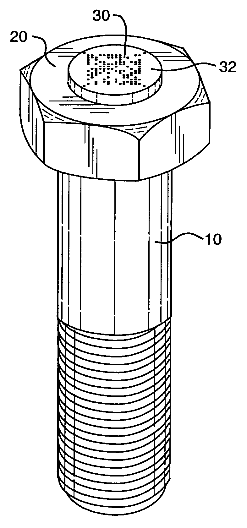
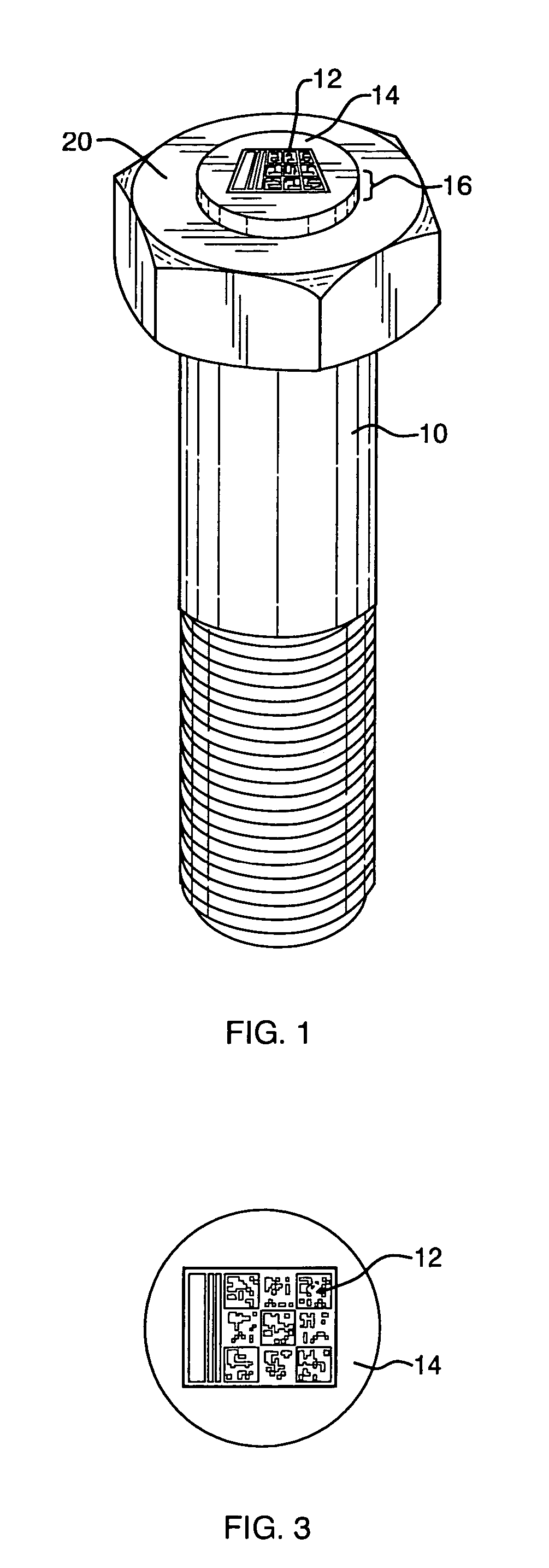
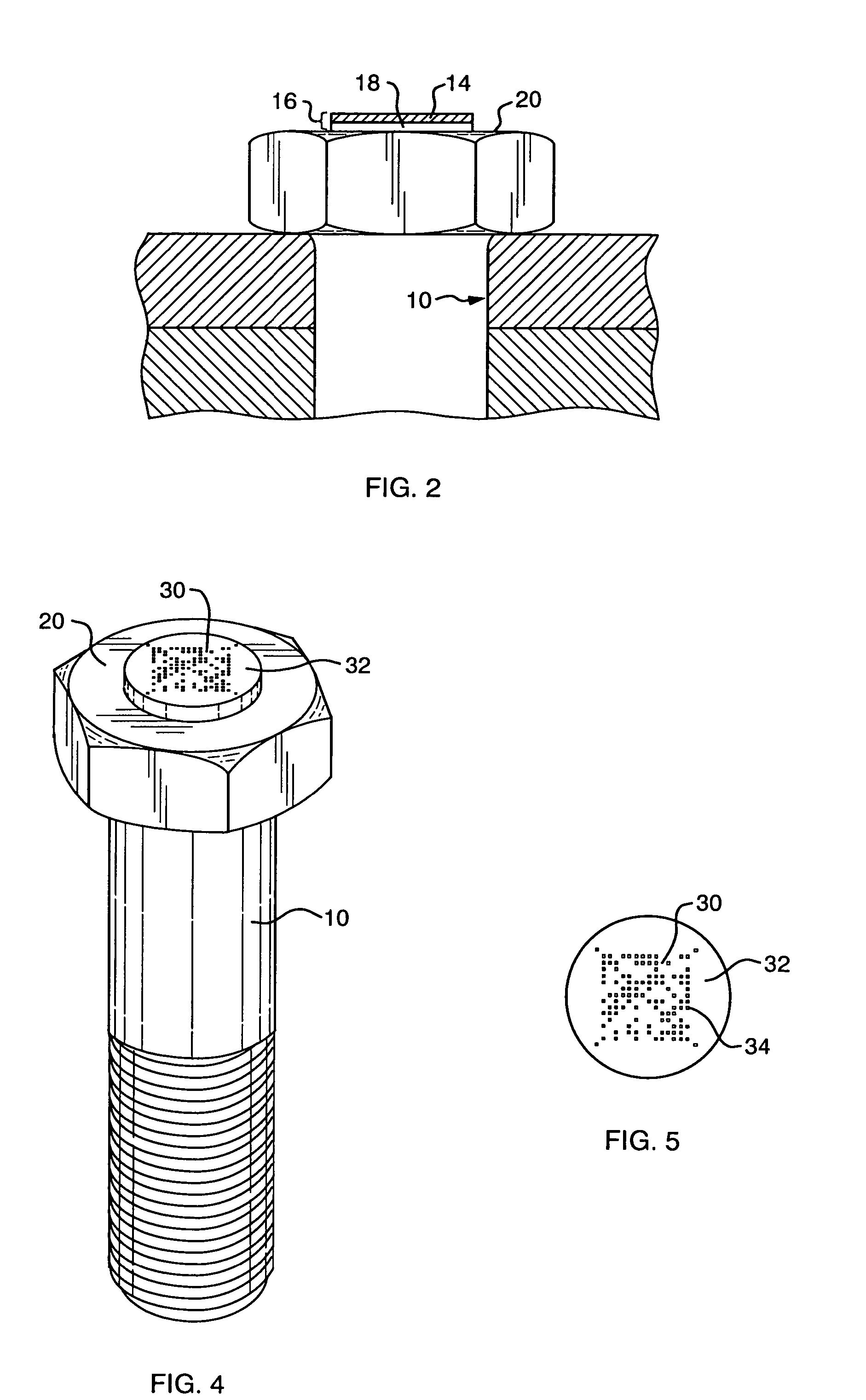
[0043]Referring now to the drawings, and more particularly to FIGS. 1, 2 and 3 thereof, a load indicating member, and more particularly, a load indicating fastener 10 is described. Load indicating fastener 10 is a fastener with a permanent piezoelectric polymer film transducer attached to one end, an example of which is disclosed in U.S. Pat. No. 4,864,001 issued to Kibblewhite, and incorporated by reference herein. The load indicating fastener of the present invention further includes a two-dimensional high-density bar code 12 on top electrode 14 of permanent ultrasonic transducer 16.

[0044]The load indicating fastener 10 is formed from a conventional bolt which has been modified to provide an indication of the tensile load, stress, elongation or other characteristic of the bolt during a tightening operation, as well as at various other times during the life of a joint. A thin piezoelectric polymer sensor 18 is permanently, mechanically and acoustically attached to end surface 20 of...

second embodiment

[0048]In a similar second embodiment of a load indicating member of the present invention, only a unique identification is encoded in bar code 12, and the ultrasonic measurement parameters associated with load indicating member 10 with this unique bar code are stored in a database, rather than encoded in the bar code itself. Since the data itself is not encoded within the code, unique bar codes can be marked on the stainless steel foil prior to cutting the disc and bonding it to the fastener to form the load indicating member. In this embodiment, the load measurement instruments require the data from the load measurement parameter database in order to make a load measurement in a pre-installed fastener.

[0049]An alternative method of providing a permanent durable bar code on the stainless steel of the top electrode is illustrated in FIGS. 4 and 5. A dot-type bar code 30, such as the proprietary “Snowflake” code available from Marconi Data Systems, Wood Dale, Ill., is marked on top el...

third embodiment

[0050]In the present invention, a load indicating member of the type disclosed in U.S. Pat. No. 5,131,276 (Kibblewhite), incorporated by reference herein, is provided in which a piezoelectric thin-film transducer is grown directly on one end of a fastener by a vacuum deposition method, such as magnetron sputtering. Alternatively, a load indicating member is provided in which a piezoelectric thin-film transducer is grown directly on foil by a vacuum deposition method, such as magnetron sputtering, and the transducer is then mechanically, electrically and acoustically attached to the fastener. Also provided is a surface on the top electrode, or elsewhere on the load indicating member, suitable for the marking of a bar code with the above-described marking methods, to provide the same function as those of the above-described embodiments of the present invention. Alternatively, an additional, thin color-contrasting layer could be vacuum deposited during the manufacturing operation. Part...


PUM

PropertyMeasurementUnit
thickaaaaaaaaaa
thickaaaaaaaaaa
diameteraaaaaaaaaa

Abstract

A load indicating member is provided with a permanent identifying mark which can be read and used to determine ultrasonic measurement parameters specific to the load indicating member to provide more precise and more reliable load measurements by compensating for differences resulting from manufacturing variations in individual load indicating members. The parameters specific to the load indicating member can be stored in coding applied to the load indicating member or in a database that can be accessed remotely, for example, using the Internet.

Description

CROSS-REFERENCE TO RELATED APPLICATION[0001]This application claims the benefit of U.S. Provisional Application No. 60 / 264,877, filed Jan. 29, 2001.BACKGROUND OF THE INVENTION[0002]This invention relates to load indicating members and, more particularly, to load indicating members, such as fasteners, having ultrasonic transducers.[0003]In many operations, it is desirable to determine the amount of longitudinal load experienced by a longitudinally stressed member. This information is particularly useful when the longitudinally stressed member is a fastener since the measurement of longitudinal load provides a verification of the existence of a proper joint.[0004]Ultrasonic load measurement is a precise measurement technique for determining load in bolted joints. Pulse-echo techniques with removable ultrasonic transducers have been used in laboratories and for quality control for over thirty years. Historically, however, the practical difficulties in achieving reliable acoustic coupli...

Claims


Application Information

Patent Timeline
Patent Type & Authority Patents(United States)
IPC IPC(8): F16B31/02G01N29/04G01N29/22
CPCG01N29/048B60N2/3095F16B31/02G01N29/227G01N2291/02854B60N2002/4405G01N2291/011G01N2291/2691B60N2002/905
Inventor KIBBLEWHITE, IAN E.
Owner INNOVATION PLUS
Why Eureka
Try Eureka