Combination gravimetric and volumetric dispenser for multiple fluids

a technology of gravimetric and volumetric dispensers, applied in liquid handling, packaging goods types, transportation and packaging, etc., can solve the problems of inefficient time for dispensing base materials and solvents, noticeable errors in paint product color, and lack of speed of nutating pumps of other types of pumps

Active Publication Date: 2006-01-31
FLUID MANAGEMENT LLC
View PDF14 Cites 80 Cited by
  • Summary
  • Abstract
  • Description
  • Claims
  • Application Information

AI Technical Summary

Benefits of technology

[0022]In another refinement, the two stage valves are connected concentrically to the manifold in an outlet of each of said two stage valves is directed downward and toward a central axis around which the two stage valves are mounted to the manifold. Using this refinement, the base materials are directed toward an axial center of the container to minimize splashing.
[0025]In yet another refinement, each two step valve comprises a cylinder that includes a first end connected to an outlet port and a second end connected to an actuator with an inlet port disposed there between and which is connected to its respective base reservoir. The actuator is connected to a first end of a rod that has a second end that serves as a low flow plug. The rod slidably passes through a first spring disposed between the actuator and the low flow plug. The rod also slidably passes through a first sleeve disposed between the first spring and the low flow plug. A first end of the first sleeve engages the first spring and the second end of the first sleeve engages a second spring. The second end of the first sleeve also is connected to a second sleeve. The second sleeve connects the first sleeve to an annular high flow plug. The second spring is trapped between the first sleeve and a fixed annular retainer. The rod also slidably passes through the second spring and second sleeve and passes through the fixed annular retainer but is fixedly connected to the fixed annular retainer. The annular retainer comprises of first end directed towards the second end of the first sleeve and a second end which supports the second spring. In a closed position, the first spring biases the low flow plug of the rod and the annular high flow plug into a ceiling engagement with the outlet port by way of biasing pressure from the first spring against the first sleeve. To move from the closed position to a low flow position, the actuator pulls the rod away from the outlet port thereby causing the first end of the annular retainer to move towards the first sleeve and moving the low flow plug portion of the rod out of ceiling engagement with the annular high flow plug. To move from the low flow position to a high flow position, the actuator continues to move the rod away from the outlet port so that the first end of the annular retainer engages the second end of the first sleeve thereby causing the first sleeve to pull the second sleeve and the high flow annular plug away from the outlet port by overcoming the bias of the first spring.

Problems solved by technology

However, the colorants must be added very precisely as a one milliliter or less error in the amount of colorant can produce a noticeable error in the color of the paint product.
While nutating pump technology has beneficial applications for the dispensing of relatively small quantities of liquids such as colorants and functional additives to a liquid formulation, nutating pumps lack the speed of other types of pumps and therefore are inefficient in terms of time when it comes to dispensing base materials and solvents.
The reason being is that paint retailers are unwilling or unable to devote the amount of space that would be required to house two separate dispensing machines, one for base materials and one for colorants.
The bulkiness of the colorant dispenser is exacerbated by the need to include a controller, such as a central processing unit, a keyboard and a monitor and cabinet space to house these items.
Further, some dispensers must include a large number of different colorants (in excess of twenty) thereby increasing the size of the cabinet that holds the canisters.
Because each store or retail facility is designed differently, many retailers are faced with the difficult task for making room for such large automated paint colorant dispensers in areas of limited space.
The use of a separate machine to carry out the processes of the '145 patent would also be very problematic and would not be well received by merchants with limited floor space.
When a retailer needs to custom mix a smaller quantity of paint using an automated dispenser designed to dispense colorants into larger five gallon containers, a smaller container is disposed so far below the dispense outlet that splashing of the colorant as it reaches the smaller container is common and problematic.
Obviously, when the colorant splashes outside of the container, the accuracy of the resulting paint color is compromised.
Further, splashing of paint colorant outside of the container receptacle also results in colorant being splattered onto the dispensing apparatus causing it to be unsightly and in need of frequent cleaning.

Method used


Image

  • Combination gravimetric and volumetric dispenser for multiple fluids
  • Combination gravimetric and volumetric dispenser for multiple fluids
  • Combination gravimetric and volumetric dispenser for multiple fluids

Examples


Embodiment Construction

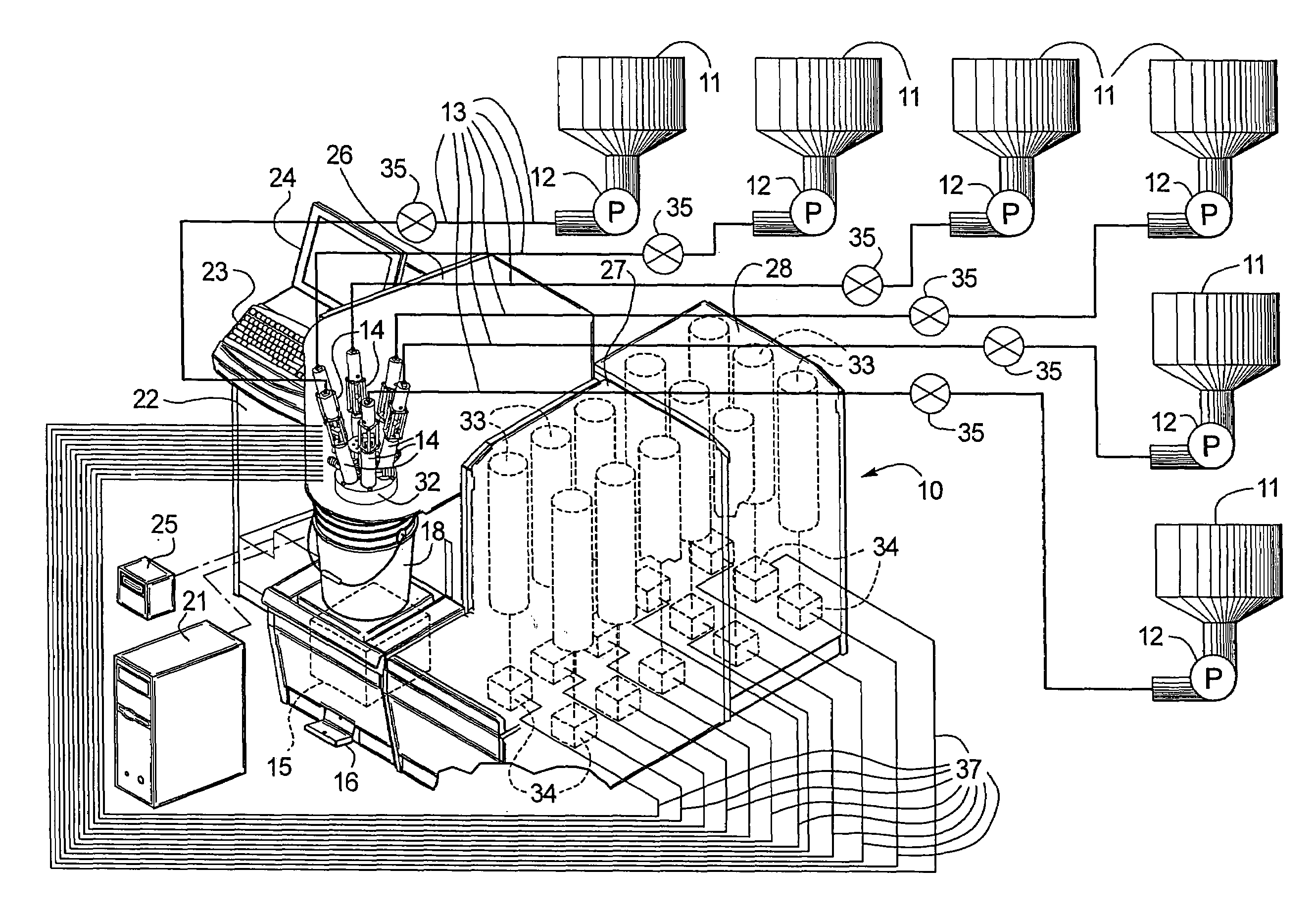
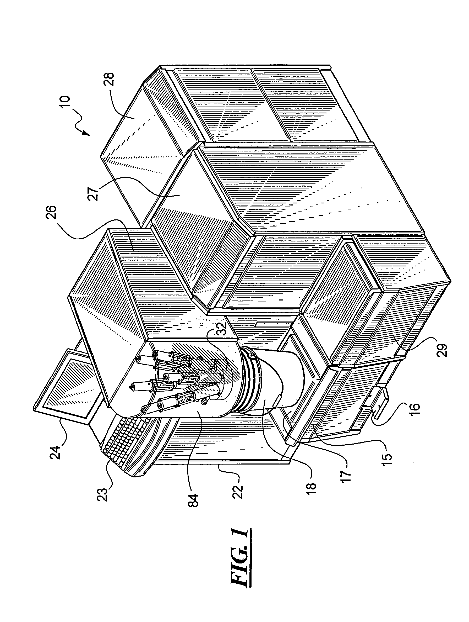
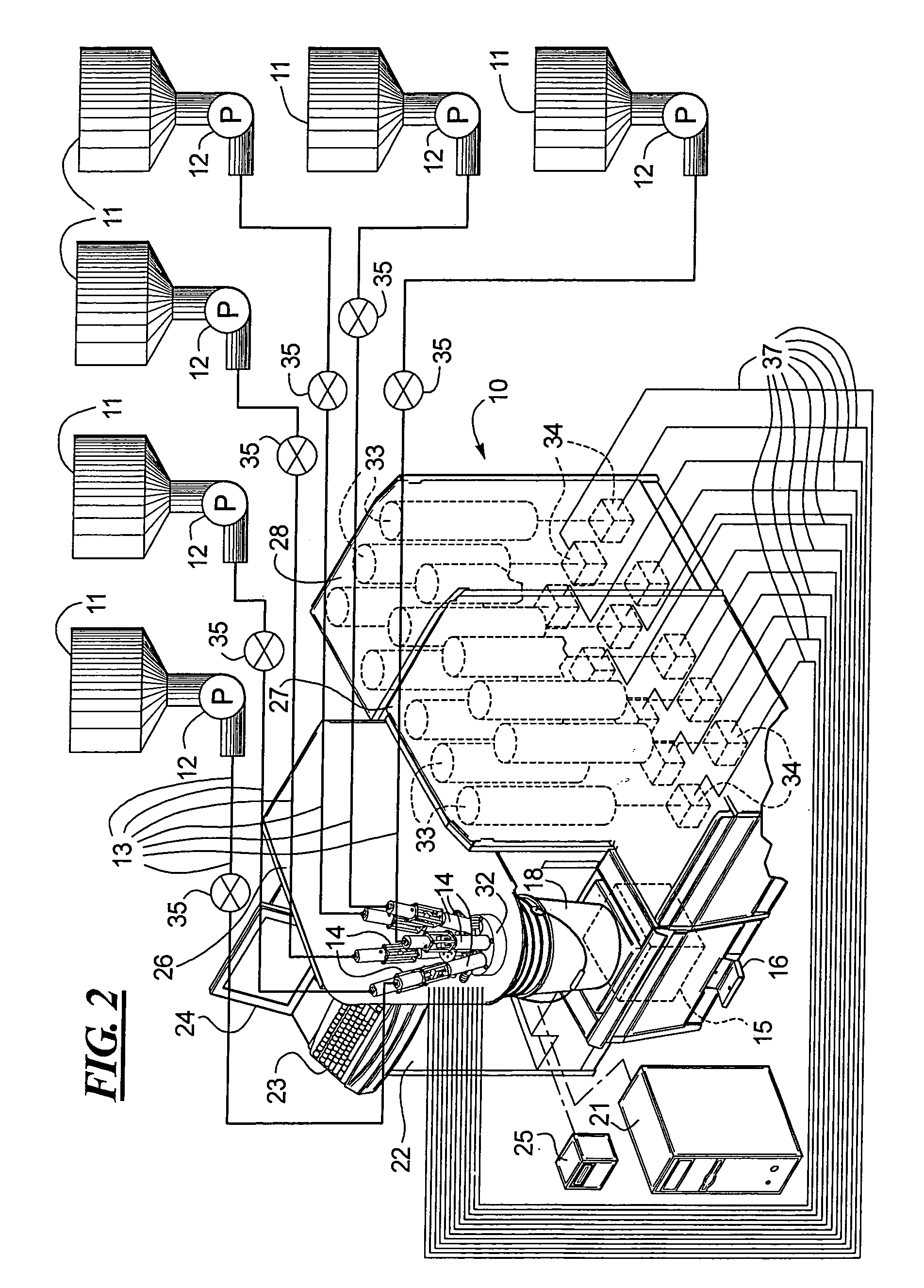
[0049]FIG. 1 illustrates, in part, a dispensing system 10 made in accordance with this disclosure. FIG. 1 is only a partial illustration because, as illustrated in FIG. 2, the dispensing system 10 also includes a plurality of base reservoirs 11, pumps 12 which are connected to the individual base reservoirs shown at 11 and conduits shown at 13 linking the base reservoirs 11 to the two step valves shown at 14, all shown in FIG. 2.

[0050]Returning to the dispensing system 10 shown in FIG. 1, the system 10 includes a scale 15 which may be adjusted vertically by way of the foot pedal 16 so that the horizontal surface 17 may be raised or lowered to accommodate a larger or smaller container than the one shown at 18 in FIG. 1. As shown in FIG. 2, the scale 15 is linked to a controller 21 which is housed in the cabinet 22 disposed below the keyboard 23 and monitor 24 as shown in FIG. 1. Referring to FIGS. 1 and 2 together, it will also be noted that a proportional control or a proportional c...


PUM

PropertyMeasurementUnit
distanceaaaaaaaaaa
distanceaaaaaaaaaa
distanceaaaaaaaaaa

Abstract

A combination gravimetric and volumetric fluid dispenser is disclosed which includes a scale linked to a controller. The controller is linked to a plurality of two stage valves which control the dispensing of large quantities of base materials. The controller is also linked to a plurality of nutating pumps which together with the controller controls the dispensing of smaller quantities of additive materials. The dispensing system disclosed is particularly useful for paints or other liquid formulations where larger quantities of base materials are added and which can be added by weight and whereby precise measurements of the larger base materials is not particularly required. However, the incorporation of nutating pumps and the addition of smaller amounts of additives by volume using the nutating pumps enables precise dispensing of the additives, such as colorants for paint. The larger containers or reservoirs of base material may be disposed at a remote location from the dispensing apparatus. The dispensing apparatus is also preferably designed with a modular configuration as shown and described. For viscous materials, an improved dispensing method is disclosed whereby viscous base material is added to the container first followed by smaller amounts of additives followed by additional dispensing of viscous base materials. By sandwiching the smaller amounts of additives between layers of base materials, an improved mix ability results for viscous materials such as base materials of paints and colorants.

Description

BACKGROUND[0001]1. Technical Field[0002]An improved dispensing system and a process for dispensing various liquids of dispensing system a liquid formulation are shown and described. More specifically, an improved dispensing system is disclosed for combining multiple liquids and / or slurries of a liquid formulation whereby the multiple liquids include one or more base fluids which constitute a majority of the formulation and which can be dispensed by weight because the exact amount of such base ingredients is not important and further whereby the formulation includes smaller amounts of additives which must be dispensed precisely and, accordingly, are dispensed precisely by volume using the disclosed dispenser. The dispensing system includes a scale for measuring the amount of base materials added and a plurality of nutating pumps for accurately dispensing smaller amounts of additives. A controller is used to control the operation of valves through which the base materials are dispense...

Claims


Application Information

Patent Timeline
Patent Type & Authority Patents(United States)
IPC IPC(8): B65B1/30B01F13/10B01F15/02B01F15/04F16K3/34
CPCB01F13/1055B01F15/00149B01F15/00194B01F15/0247F16K3/34B01F15/0445B01F15/0479B01F15/0261B01F2015/0221B01F2215/005B01F33/84B01F35/21112B01F35/2117B01F35/715B01F35/717613B01F35/718051B01F35/881B01F35/883B01F2101/30
Inventor KAUFHOLD, KENNETH R.PAGE, STEVEN R.RUMMELHART, DONALD A.
Owner FLUID MANAGEMENT LLC
Why Eureka
Try Eureka