Flow control element including elastic membrane with pinholes

a flow control and elastic membrane technology, applied in the direction of drinking vessels, drip catchers, transportation and packaging, etc., can solve the problems of choking and coughing, bottle-fed babies often experience feeding related problems, and fail to achieve the fluid flow rate through the membrane

Inactive Publication Date: 2006-01-31
MEDELA HLDG AG
View PDF35 Cites 23 Cited by
  • Summary
  • Abstract
  • Description
  • Claims
  • Application Information

AI Technical Summary

Benefits of technology

[0007]The present invention is directed to a flow control element (e.g., a baby bottle nipple or a child sippy cup flow control valve) that includes a tube-like wall section defining a flow channel, and a membrane supported in the flow channel such that membrane impedes flow through the flow channel to an external region. The membrane is formed from a suitable elastomeric material (e.g., soft rubber, thermoplastic elastomer, or silicone) that is punctured to form multiple, substantially round pinholes that remain closed to prevent fluid flow through the membrane and flow channel under normal atmospheric conditions (i.e., while the membrane remains non-deformed), thereby providing a desired “no drip” characteristic. In contrast, when subjected to an applied pressure differential (e.g., when sucked on by a child), the membrane stretches (deforms), thereby causing some or all of the pinholes to open and to facilitate fluid flow rate through the membrane. Because the amount that the pinholes open, and the associated fluid flow through the pinholes, is related to the applied pressure differential, the present invention provides a flow control element that automatically adjusts its fluid flow rate to the needs of a growing child. In addition, because the pinholes are substantially round, the pinholes resist the clogging and tearing problems associated with slit-type flow control elements.
[0008]According to an embodiment of the present invention, the membrane is substantially flat (planar) and arranged such that a force generated by the applied pressure differential is perpendicular to a plane defined by the non-deformed membrane. By providing a flat membrane, sufficient deformation of the membrane (and associated opening of the pinholes) is achieved in response to a relatively small sucking force (pressure). Formation of the pinholes is also easier when the membrane is flat.
[0011]According to another embodiment of the present invention, the pinholes are formed such a first group of pinholes opens at a lower applied pressure differential than a second group of pinholes, which open at a somewhat higher applied pressure. Such different sized pinholes produce relatively low flow rates at low sucking pressures (i.e., because larger pinholes open while smaller pinholes remain essentially closed), and substantially greater flow rates at high sucking pressures (i.e., because both large and small pinholes are opened), thereby facilitating the production of a baby bottle nipple that can be used throughout a child growth from infant to toddler.

Problems solved by technology

A problem associated with conventional baby bottle nipples is that, unlike natural female breasts, the quantity of formula / milk drawn through the nipple is relatively fixed, which causes a parent to periodically replace relatively low flow nipples with higher flow nipples as a child's feeding needs increase.
Unlike breast-fed babies, bottle-fed babies often experience feeding related problems associated with conventional nipple products that exhibit substantially fixed milk flow rates.
A problem arises when a baby's draw rate fails to match the particular nipple from which that baby is being fed.
For example, when a newborn infant is fed from a toddler nipple, the high flow rate can result in choking and coughing.
Conversely, when a toddler is presented with a newborn baby's nipple, the low flow rate can cause frustration.
In many instances, parents experience a great deal of anxiety trying to match the correct nipple to a baby's ever-changing milk flow demand.
A problem associated with “no drip” flow control elements (i.e., sippy cup flow control valves and baby bottle nipples) that are formed by cutting or molding slits in elastomeric material is that these slits typically fail or become clogged over time, which results in undesirable leakage and / or failure.
The problem with such slit-type sippy cup valves and baby bottle nipples as is that the elastomeric material in the region of the slits can fatigue and / or become obstructed over time, and the resulting loss of resilience can cause leakage when the slit flaps fail to fully close after use.
This failure of the slit flaps to close can be caused by any of several mechanisms, or a combination thereof.
First, repeated shearing forces exerted at the end of each slit due to repeated use can cause tearing of the elastomeric material in this region, thereby reducing the resilient forces needed to close the slit flaps after use.
Second, thermal cycling or mechanical cleaning (brushing) of the elastomeric material due, for example, to repeated washing, can cause the elastomeric material to become less elastic (i.e., more brittle), which can also reduce the resilience of the slit flaps.
Third, solid deposits left by liquids passing through the slits can accumulate over time to impede the slit flaps from closing fully.

Method used


Image

  • Flow control element including elastic membrane with pinholes
  • Flow control element including elastic membrane with pinholes
  • Flow control element including elastic membrane with pinholes

Examples


Embodiment Construction

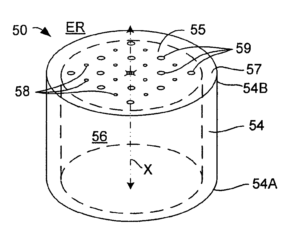
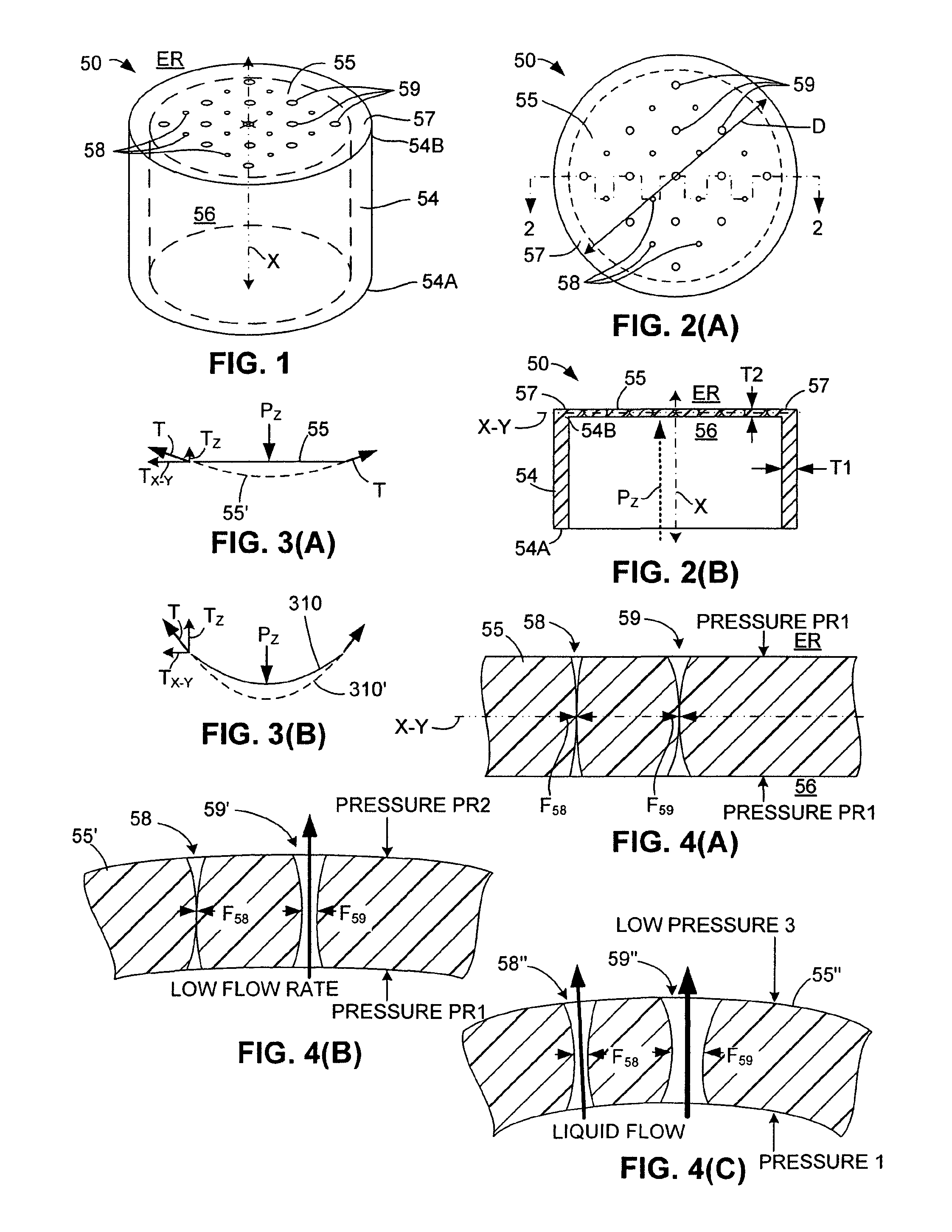
[0031]FIG. 1 is a perspective view showing a generalized flow control element 50 including a wall section 54 and a membrane 55. FIGS. 2(A) and 2(B) show flow control element 50 in top plan and cross-sectional side views, respectively, where FIG. 2(B) is taken along section line 2—2 of FIG. 2(A).

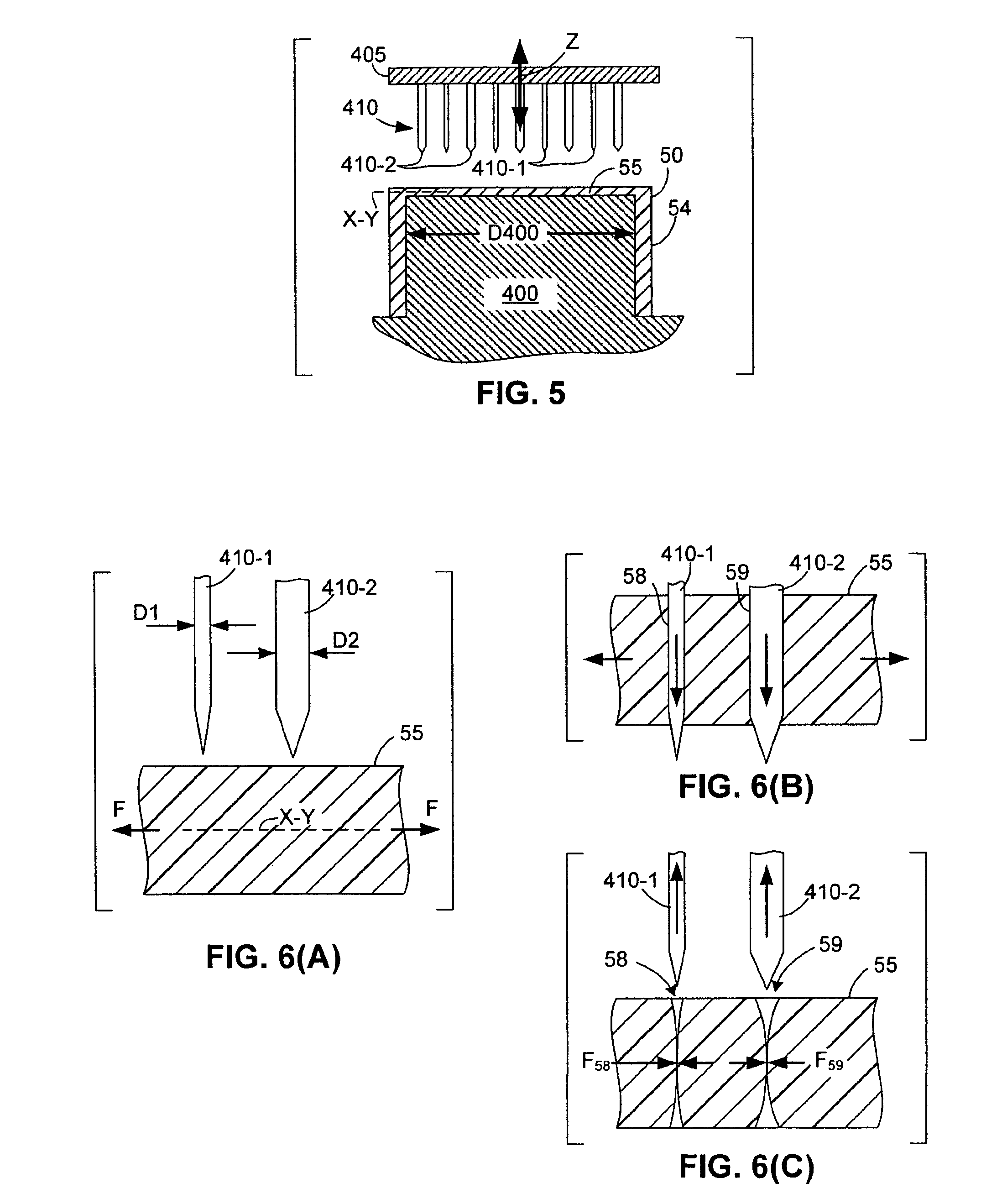
[0032]Wall section 54 is a tube-like structure defining a fluid flow channel 56 that extends generally along a central axis X between a lower (first) end 54A and an upper end 54B of wall section 54. As indicated in FIG. 2(A), in one embodiment wall section 54 has a circular cross section having a diameter D.

[0033]Membrane 55 is formed form a relatively elastic material and is connected to wall section 54 such that membrane 55 is disposed across fluid flow channel 56 to impede flow between fluid flow channel 56 and an external region ER (i.e., either from fluid flow channel 56 to external region ER, or from external region ER to fluid flow channel 56). In the disclosed embodiment, membrane 55 ...


PUM


Abstract

A flow control element (e.g., a baby bottle nipple or a child sippy cup flow control valve) that includes a tube-like wall section defining a flow channel, and a substantially flat membrane supported by the wall section such that membrane impedes flow through the flow channel to an external region. The membrane punctured to form multiple, substantially round pinholes arranged in a two-dimensional pattern that remain closed to prevent fluid flow under normal atmospheric conditions, and open and to facilitate fluid flow rate through the membrane under an applied pressure differential (e.g., when sucked on by a child). The wall section has a greater rigidity than the membrane (which is formed from a relatively highly elastic material). Different sized pinholes are produced using different sized pins, thereby facilitating different flow rates in response to different applied pressure differentials. The pinholes are generated while stretching the membrane in a radial direction.

Description

RELATED APPLICATION[0001]The present application is a continuation-in-part of U.S. patent application Ser. No. 10 / 351,137 filed by James W. Holley, Jr. on Jan. 24, 2003.FIELD OF THE INVENTION[0002]The present invention relates to fluid flow control devices for beverage containers, and more specifically it relates to “no drip” flow control elements for baby bottles and child sippy cups.RELATED ART[0003]Baby bottles and sippy cups represent two types of beverage containers that utilize flow control devices to control the ingestion of beverage in response to an applied sucking force. Baby bottle assemblies utilize nipples to pass baby formula or milk from the bottle to a child (i.e., infant or toddler) in response to a sucking force (pressure) applied by the child on the nipple. Sippy cups are a type of spill-resistant container typically made for children that include a cup body and a screw-on or snap-on lid having a drinking spout molded thereon. An inexpensive flow control element, ...

Claims


Application Information

Patent Timeline
Patent Type & Authority Patents(United States)
IPC IPC(8): A61J11/00
CPCA61J11/009A61J11/001A61J9/00B65D23/04B65D23/06B65D25/38B26F1/24B65D47/20
Inventor HOLLEY, JR., JAMES W.
Owner MEDELA HLDG AG
Why Eureka
Try Eureka