Hydraulic braking system operated by an external force

Inactive Publication Date: 2006-01-31
DAIMLER AG
View PDF16 Cites 11 Cited by
  • Summary
  • Abstract
  • Description
  • Claims
  • Application Information

AI Technical Summary

Benefits of technology

[0021]In a hydraulic braking system operated by an external force, for vehicles, in particular motor vehicles, having a primary pressure source which is fed by external energy and supplies the wheel brakes with brake pressure during normal operation, and having a foot-actuated auxiliary pressure source which supplies the wheel bra

Problems solved by technology

All the inlet and outlet valves of this braking system operated by an external force are designed as identical differential-pressure solenoid valves, so that the maximum obtainable hydraul

Method used


Image

  • Hydraulic braking system operated by an external force
  • Hydraulic braking system operated by an external force
  • Hydraulic braking system operated by an external force

Examples


Example

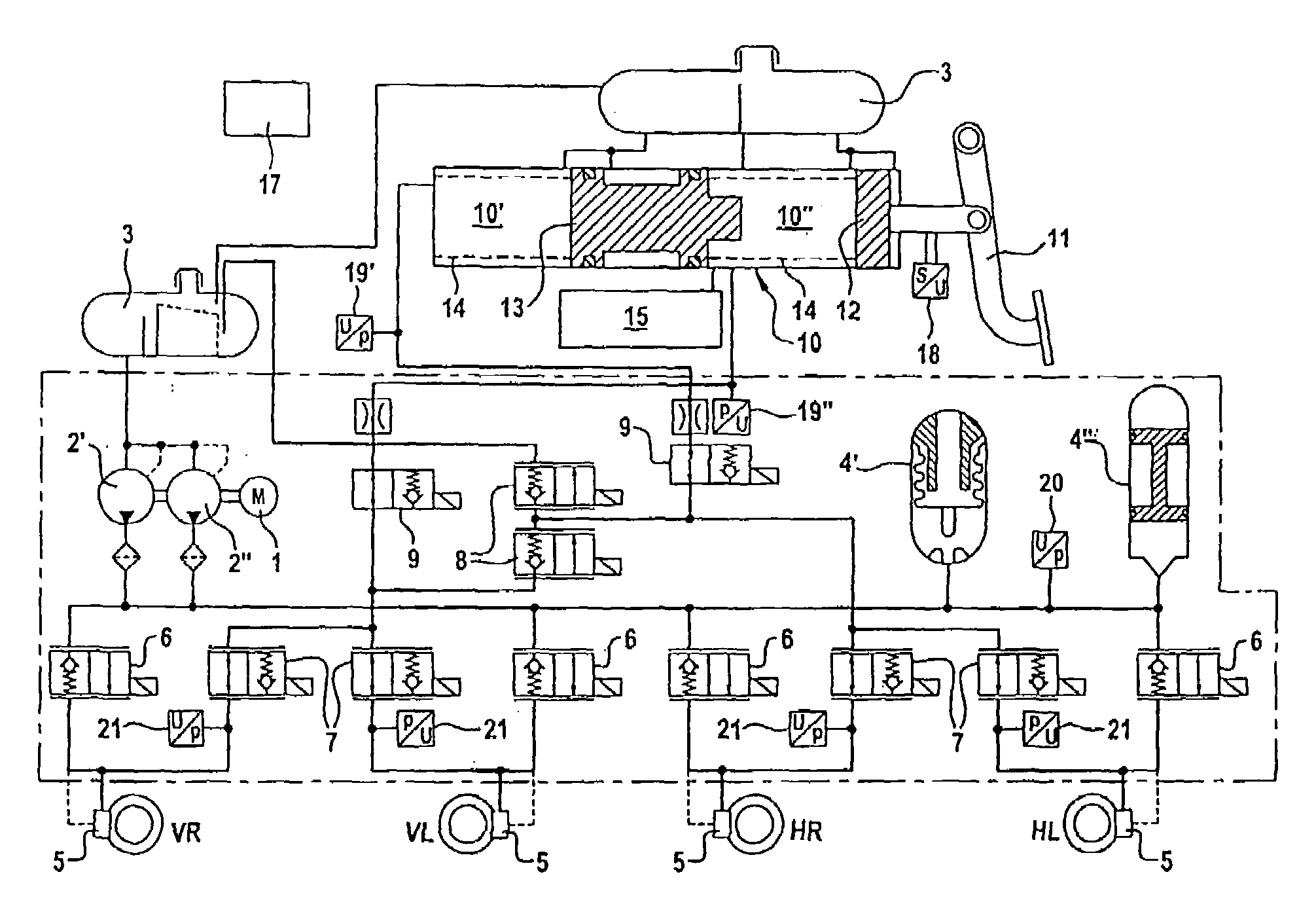
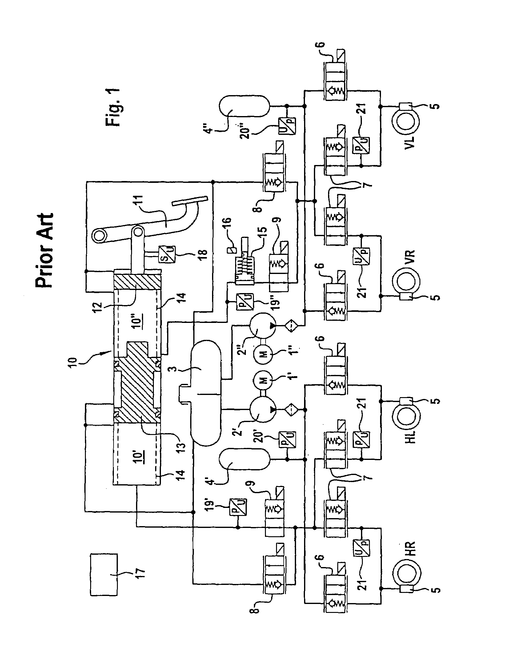
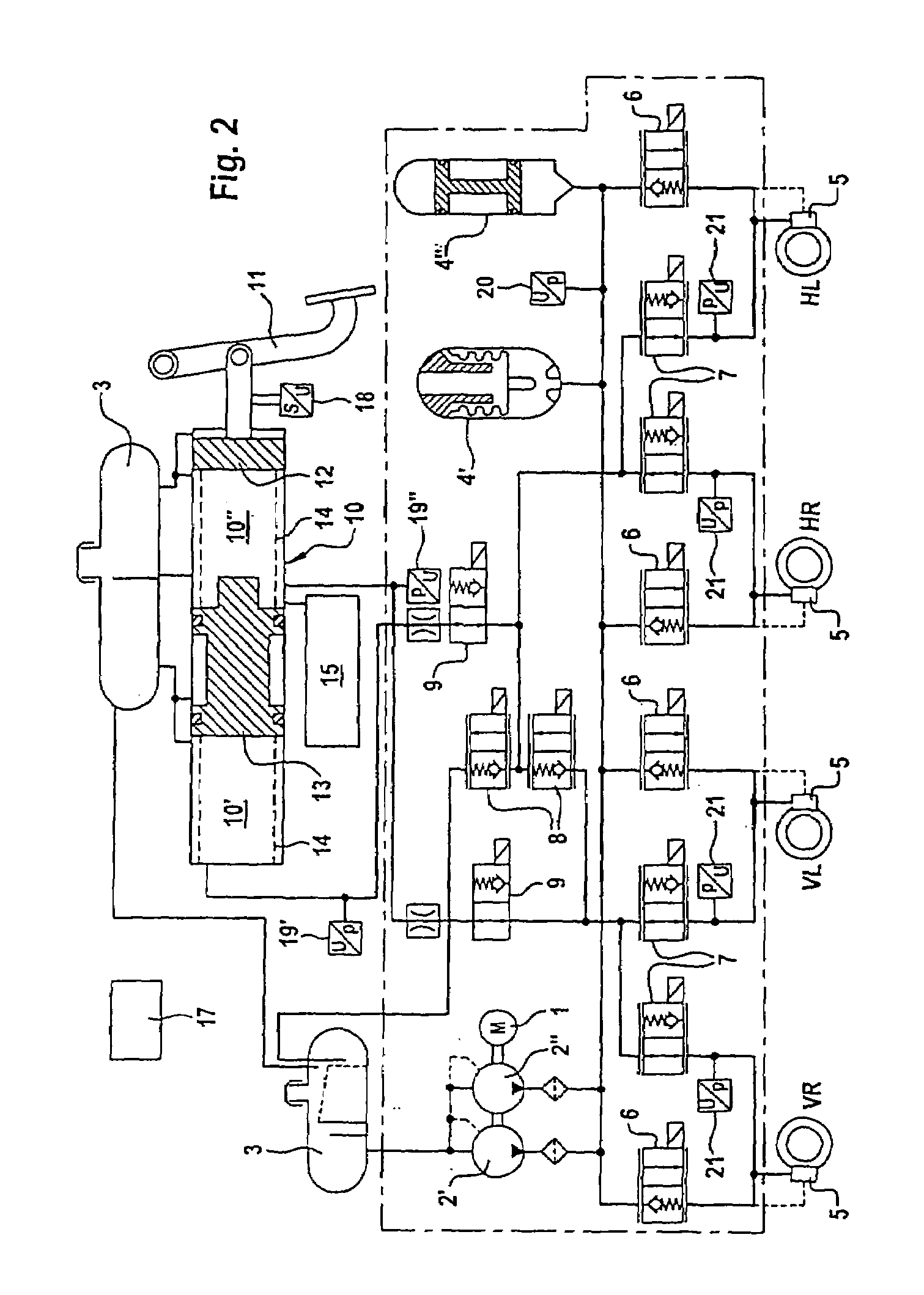
[0026]The braking system operated by an external force, illustrated in FIG. 1, includes two hydraulic pumps 2′ and 2″, which are driven by separate electric motors 1′ and 1″ and which are connected in each case on the suction side to a chamber of an essentially pressureless hydraulic reservoir 3 and on the delivery side to a hydraulic pressure accumulator 4′ and 4′.

[0027]Each pump 2′ or 2″ or each pressure accumulator 4′ or 4″ is assigned actuating assemblies of the wheel brakes of the front wheels VR, VL and of the rear wheels HR and HL, said actuating assemblies being displacer assemblies 5, typically known as wheel brake cylinders.

[0028]Each displacer assembly 5 can be connected to the assigned hydraulic pump 2′ or 2″ or to the assigned pressure accumulator 4′ or 4″ via a normally closed controllable inlet valve 6. A normally open controllable connecting valve 7 is arranged in parallel with the respective inlet valve 6. In each displacer assembly 5, the connecting valves 7 of the...


PUM


Abstract

In a hydraulic braking system operated by an external force, for vehicles, in particular motor vehicles, having a primary pressure source which is operated by external energy and provide brake pressure to the wheel brakes during normal operation, and which also has a foot-actuated auxiliary pressure source which supplies the wheel brakes with brake pressure during emergency operation, to increase the degree of safety, a special hydraulic circuit is provided wherein, during emergency operation, only comparatively few valves between the wheel brakes and a hydraulic reservoir have to be closed so as to be free of leakage, while operational safety is increased by the valves being connected in series.

Description

[0001]This is a Continuation-In-Part Application of international application PCT / EP02 / 08187 filed Jul. 23, 2002 and claiming the priority of German application 101 47 150.5 filed Sep. 25, 2001.BACKGROUND OF THE INVENTION[0002]The invention relates to a hydraulic braking system operated by an external force, for vehicles, in particular motor vehicles, with at least two axles or axle lines, with[0003]a pressureless or low-pressure-side hydraulic reservoir,[0004]at least one primary pressure source which is fed by external energy and is connected to the hydraulic reservoir for the supply of hydraulic medium,[0005]an auxiliary pressure source which is independent of the primary pressure source and can be actuated by foot or hand and which is connected to the hydraulic reservoir for the supply of a hydraulic medium and the delivery side of which communicates with the hydraulic reservoir in the non-actuated state of the auxiliary pressure source,[0006]displacer assemblies, which are assi...

Claims


Application Information

Patent Timeline
IPC IPC(8): B60T8/40B60T8/48B60T8/00B60T8/26B60T8/34B60T8/36B60T13/68
CPCB60T8/26B60T8/4081B60T8/4054B60T8/34
Inventor WOLL, PETER
Owner DAIMLER AG
Why Eureka
Try Eureka