Spring contact for connectors

a technology of connectors and spring contacts, which is applied in the direction of coupling contact members, coupling device details, coupling device connections, etc., can solve the problems of inefficient and costly installation of components on circuit boards, component not functionally performing, and need to disassemble or replace components on circuit boards. , to achieve the effect of easy and quick installation and easy and quick removal from circuit boards

Inactive Publication Date: 2006-01-31
TE CONNECTIVITY CORP
View PDF3 Cites 13 Cited by
  • Summary
  • Abstract
  • Description
  • Claims
  • Application Information

AI Technical Summary

Benefits of technology

[0009]In view of the shortcomings of the prior art, it is an object of the present invention to provide an electrical contact that allows an electrical component to be easily and quickly installed on a circuit board and has sound electrical connections between the component and the board without the need for soldering of the component leads to the board contacts. It is a further object of the present invention that the electrical contact allows an electrical component to be easily and quickly removed from a circuit board without the need for desoldering of the component leads or without damaging the board contacts.

Problems solved by technology

The need to disassemble or replace components on circuit boards has become an important issue.
For example, it is inefficient and costly to install a component on a board, to only find out, after the board assembly is complete, that the component is not functionally performing.
The time and effort to disassemble, remove and replace the component is expensive and fraught with the potential for creating or causing additional problems in the circuit.
The time and effort to install a component, solder the leads to the contacts, test the component and, if the component is not functionally operable, desolder the leads and replace the component is very inefficient and expensive.
As noted, in each of the desoldering, disassembly, reassembly and resoldering steps, there is the potential for creating additional problems in the board fabrication.
Again, the soldering of the leads to ensure a sound electrical connection does not allow for quick or easy disassembly and removal of the component.

Method used


Image

  • Spring contact for connectors
  • Spring contact for connectors
  • Spring contact for connectors

Examples


Embodiment Construction

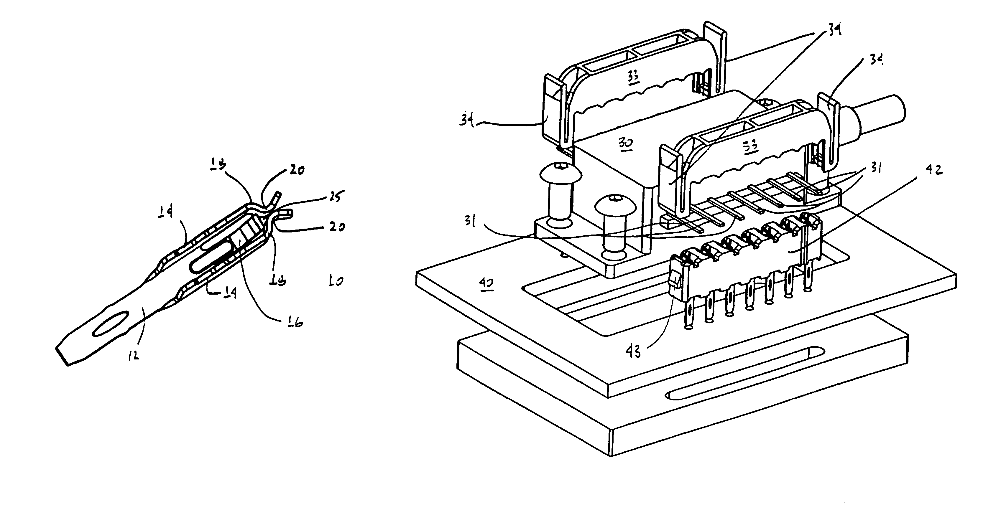
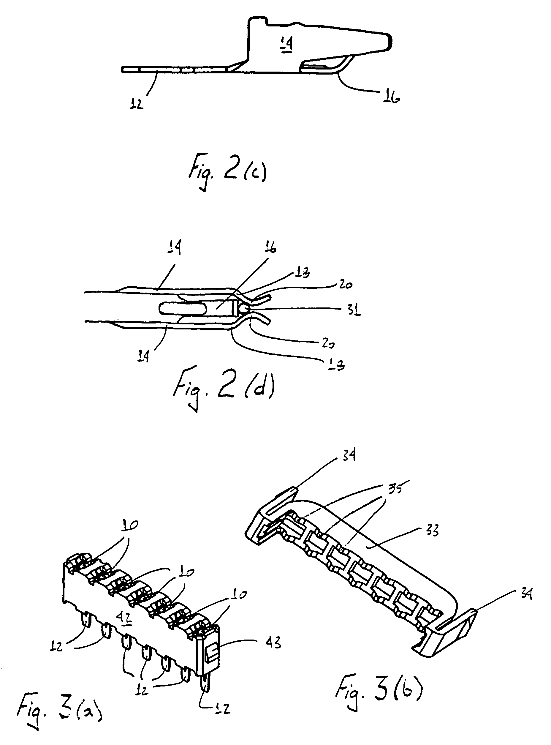
[0045]The present invention is directed to an electrical contact used to ensure sound electrical connections between an electrical component and a circuit board to which the electrical component is to be assembled. The present invention also is directed to an electrical contact assembly that is to be mounted to a circuit board, where the noted contact is used to make the electrical connection between the electrical component and the circuit board. Example electrical components that the electrical contact may be used with, and which are disclosed in detail herein, include, without limitation, laser pump and laser diodes packages.

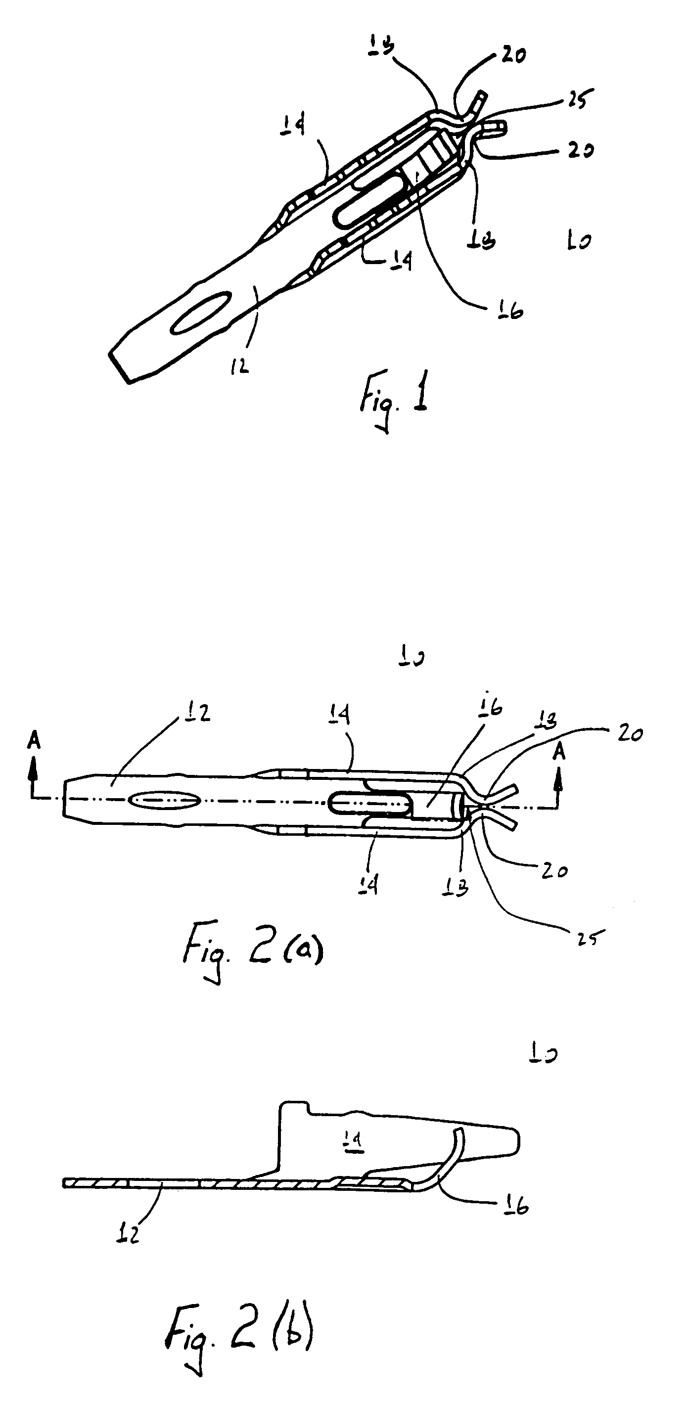
[0046]The inventive electrical contact has three primary structural elements. The contact elements include a body section, two flexible arms and a center section. The shape and structure of the contact elements is designed such that each contact holds and forms a strong electrical connection with one lead of an electrical component to be assembled on the circ...


PUM


Abstract

A spring contact design used to connect varied electrical components to circuit boards such that the components may be installed onto the board and thereafter removed without soldering and desoldering of the component leads is disclosed. The inventive contacts use integral flexible elements and appropriate contact element shaping to ensure solid multiple electrical connection points between the contact and the electrical component lead. With the use of the inventive spring contacts, components may be easily installed onto a circuit board and tested to ensure functional performance and, if necessary, may be removed or replaced without the need for time consuming soldering and desoldering of the component leads to the board contacts. The inventive contacts are designed to ensure sound electrical connection with component leads of different cross sections, shapes and sizes. Use of the inventive contacts in housings sized and shaped for different electrical components are also disclosed.

Description

CROSS REFERENCE TO RELATED APPLICATION[0001]This application is a continuation of U.S. application Ser. No. 09 / 747,608, filed Dec. 22, 2000, now U.S. pat. No. 6,802,748.[0002]This invention generally relates to electrical component connectors and contacts. More particularly, the present invention relates to an inventive three point contact design that may be used to connect varied electrical components to circuit boards such that the components may be assembled or installed on the circuit board and removed from the board without the need for time consuming soldering and desoldering of the component leads. The inventive contacts use flexible integral spring elements and appropriate contact element shaping to ensure a solid electrical connection between the printed circuit board and the electrical component leads. With the use of the inventive spring contacts, components may be easily installed on a board and tested, and, if necessary, may later be removed or replaced without the need...

Claims


Application Information

Patent Timeline
Patent Type & Authority Patents(United States)
IPC IPC(8): H01R4/48H01R12/04H01R13/115H01R13/24
CPCH01R13/115H01R13/24
Inventor WERTZ, DARRELL LYNNBRANDBERG, PHILIP CLAYYOHN, BRENT DAVID
Owner TE CONNECTIVITY CORP
Why Eureka
Try Eureka