Adjustable rod and connector device and method of use

a technology of adapter and connector, which is applied in the field of adapter rod and connector, can solve the problems of prior art failing to provide a low-profile device and prior art failing to provide pedicle screw to the adapter rod connector, and achieve the effect of reducing the displacement of bodily tissu

Inactive Publication Date: 2006-01-31
RITLAND STEPHEN
View PDF121 Cites 361 Cited by
  • Summary
  • Abstract
  • Description
  • Claims
  • Application Information

AI Technical Summary

Benefits of technology

[0007]The present invention addresses the shortcomings of the prior art. More specifically, implant assemblies and / or components of an implant are provided that allow a surgeon to adjust the implant for the patient's requirements as they are encountered during surgery, and / or which allow the surgeon to use low-profile implant components that result in minimal displacement of bodily tissue.
[0012]It is further desirable to provide a low-profile connector that can be easily used in combination with a shank of a bone screw. In a separate embodiment, low profile connector is provided that utilizes an interference-type fit to secure the connector to the shank of the bone screw. Thus, it is one aspect of the present invention to provide a connector device for a bone screw, the connector device comprising a clamp that includes an upper section and a lower section separated by a slot. The upper section includes a first aperture and the lower section includes a second aperture substantially aligned with the first aperture, where the first and second apertures are sized to accommodate a shank of the bone screw. The connector further includes a tightening member operatively connected to the upper section and the lower section. The tightening member tightens the clamp and reduces the size of the slot between the upper section and the lower section. This secures the shank of the bone screw within the device.

Problems solved by technology

The prior art fails to provide a low-profile device that allows the rod length to be easily adjusted during implantation with a minimal amount of effort by the installing surgeon.
The prior art also fails to provide pedicle screw to rod connectors that can be easily adjusted at the time of implantation.

Method used


Image

  • Adjustable rod and connector device and method of use
  • Adjustable rod and connector device and method of use
  • Adjustable rod and connector device and method of use

Examples


Embodiment Construction

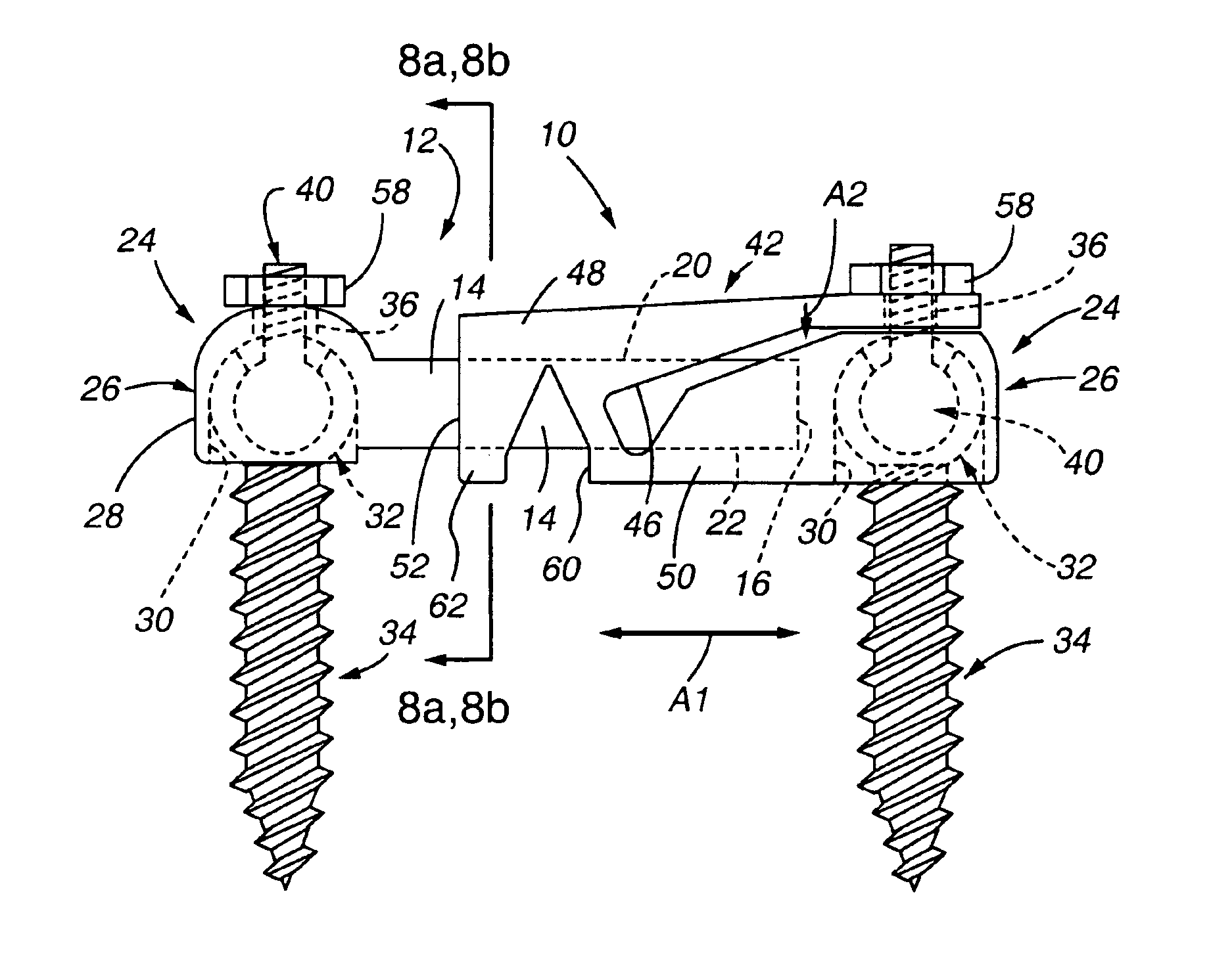
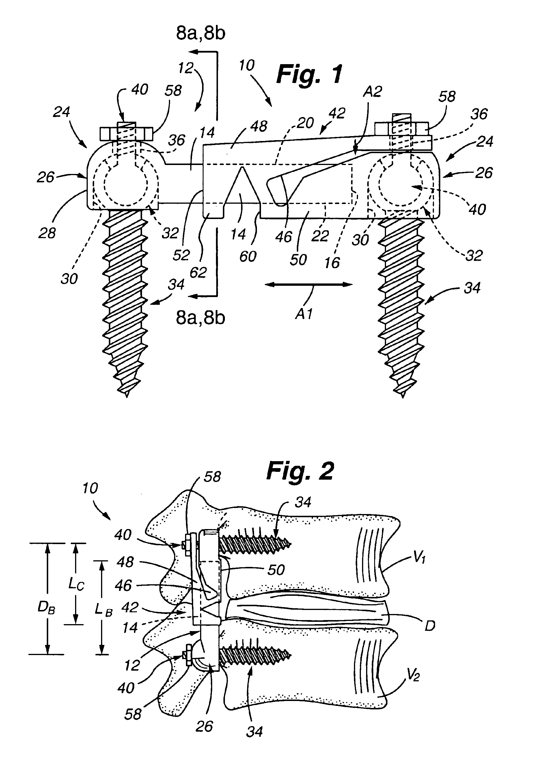
[0050]Referring to FIG. 1, a first embodiment of an adjustable rod implant 10 is shown. The adjustable rod implant 10 is preferably a multi-piece implant, and more preferably, a two-piece rod implant. By way of example and without limitation, the adjustable rod implant 10 can be used as a structural bridge to span a section of bone, or to span a distance between two portions of bone, or to span a distance between two different bones. As shown in FIG. 2, in one anticipated use, the adjustable rod implant 10 can be used as a vertebral bridge to span at least one intervertebral disc D between two vertebra V1 and V2. Accordingly, by way of illustration and without intending to limit the possible uses of the present invention, the examples of usage presented herein are generally directed toward spanning at least one intervertebral disc.

[0051]The adjustable rod implant 10 is preferably attached to the subject vertebrae using pedicle screws, with a connector interconnecting the pedicle scr...


PUM


Abstract

A low-profile surgical rod implant device is provided that allows the length of a rod spanning two bone screws to be adjusted at the time of implantation. In a separate aspect of the invention, the rod implant device can be secured by tightening and securing an end of the rod implant device at one of the bone screws. Embodiments are provided for use with polyaxial pedicle screws and substantially straight shank pedicle screws in spinal applications. In a separate aspect of the invention, a bone screw connector having an interference type fit is also provided. A method for implanting the device is also provided.

Description

CROSS REFERENCE AND PRIORITY CLAIMS TO RELATED APPLICATION[0001]This application is a continuation-in-part of, and priority is claimed to, U.S. patent application Ser. No. 10 / 262,574 filed Sep. 30, 2002, entitled “Connection Rod For Screw or Hook Polyaxial System And Method of Use”, which claimed priority to U.S. Provisional Patent Application No. 60 / 325,809 filed Sep. 28, 2001, entitled “Connection Rod For Screw or Hook Polyaxial System And Method of Use”; priority is also claimed to U.S. Provisional Patent Application No. 60 / 450,179 filed Feb. 25, 2003 entitled “Connection Rod For Screw or Hook Polyaxial System And Method of Use”, and to U.S. Provisional Patent Application No. 60 / 460,195 filed Apr. 4, 2003 entitled “Sliding Connector”. The entire disclosures of these applications are considered to be part of the disclosure of the present application and are hereby incorporated by reference in their entirety. Cross reference is also made to U.S. patent application Ser. No. 09 / 898,4...

Claims


Application Information

Patent Timeline
Patent Type & Authority Patents(United States)
IPC IPC(8): A61B17/70A61B17/56A61FA61F2/30
CPCA61B17/7007A61B17/7014A61B17/7004Y10T403/7077A61B17/7037
Inventor RITLAND, STEPHEN
Owner RITLAND STEPHEN
Why Eureka
Try Eureka