Spring contact plate

a spring contact plate and end fitting technology, applied in the direction of vehicle maintenance, vehicle cleaning, cleaning equipment, etc., can solve the problems of lack of lv standardization driven by an agency or industry group, difficult to maneuver the movable vacuum cleaner to various locations in the house, and inability to always be practical, so as to achieve good electrical contact

Inactive Publication Date: 2010-09-30
FLEXIBLE TECH INC
View PDF7 Cites 0 Cited by
  • Summary
  • Abstract
  • Description
  • Claims
  • Application Information

AI Technical Summary

Benefits of technology

[0013]One group of fingers are generally triangular in configuration with a tip and two side edges extending toward said second edge. This first group of fingers extend from the side edge of the spring contact place over the outside surface of the cylindrical member and a portion of the end fitting where the cylindrical member is connected to the end fitting. The second type of finger extends a short distance from the edge and contacts a corresponding raised pin on the housing. This second type of finger has a raised angular tip that extends upwardly of the top surface of the contact spring. The pin that is on the housing prevents axial movement of the spring when the spring is inserted into a Type A wall inlet or a powered head. The configuration of the pin and the respective tab on the contact spring plate causes the spring plate to flex outwardly in a radial direction with minimum axial displacement. This arrangement and the arrangement of the other fingers on the spring contact plate provide good electrical contact with the LV electrical contacts in the Type A inlet.

Problems solved by technology

Many times, these people find it more difficult to maneuver the movable vacuum cleaners to various locations in the house, such as up and down stairs or tight spaces, as they are using it.
This lack of LV standardization driven by an agency or industry group is the crux of the problem as there is no uniformity in the connectors.
Ideally, a single wall end fitting would be able to fit all Type A wall valves and function properly, but due to omissions and ambiguities in the standards, this is not always possible in practice.
The challenge to this implementation is that the mating implementations in the Type A wall valves vary greatly; there are fixed and spring loaded pins of varying diameters and positions with differing degrees of flexibility and range of motion.
This increases the expense in manufacturing the hose end fittings.

Method used


Image

  • Spring contact plate
  • Spring contact plate
  • Spring contact plate

Examples


Embodiment Construction

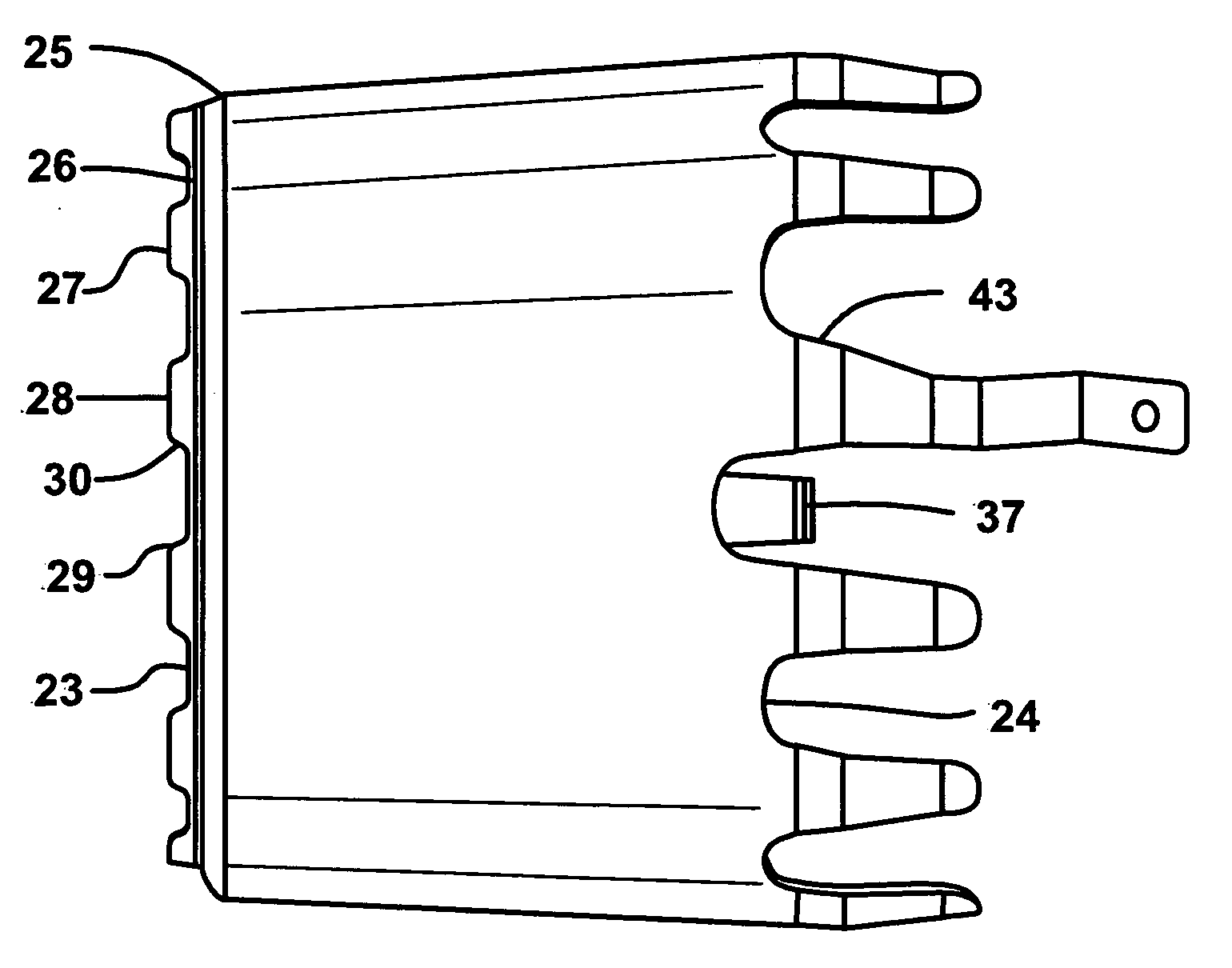
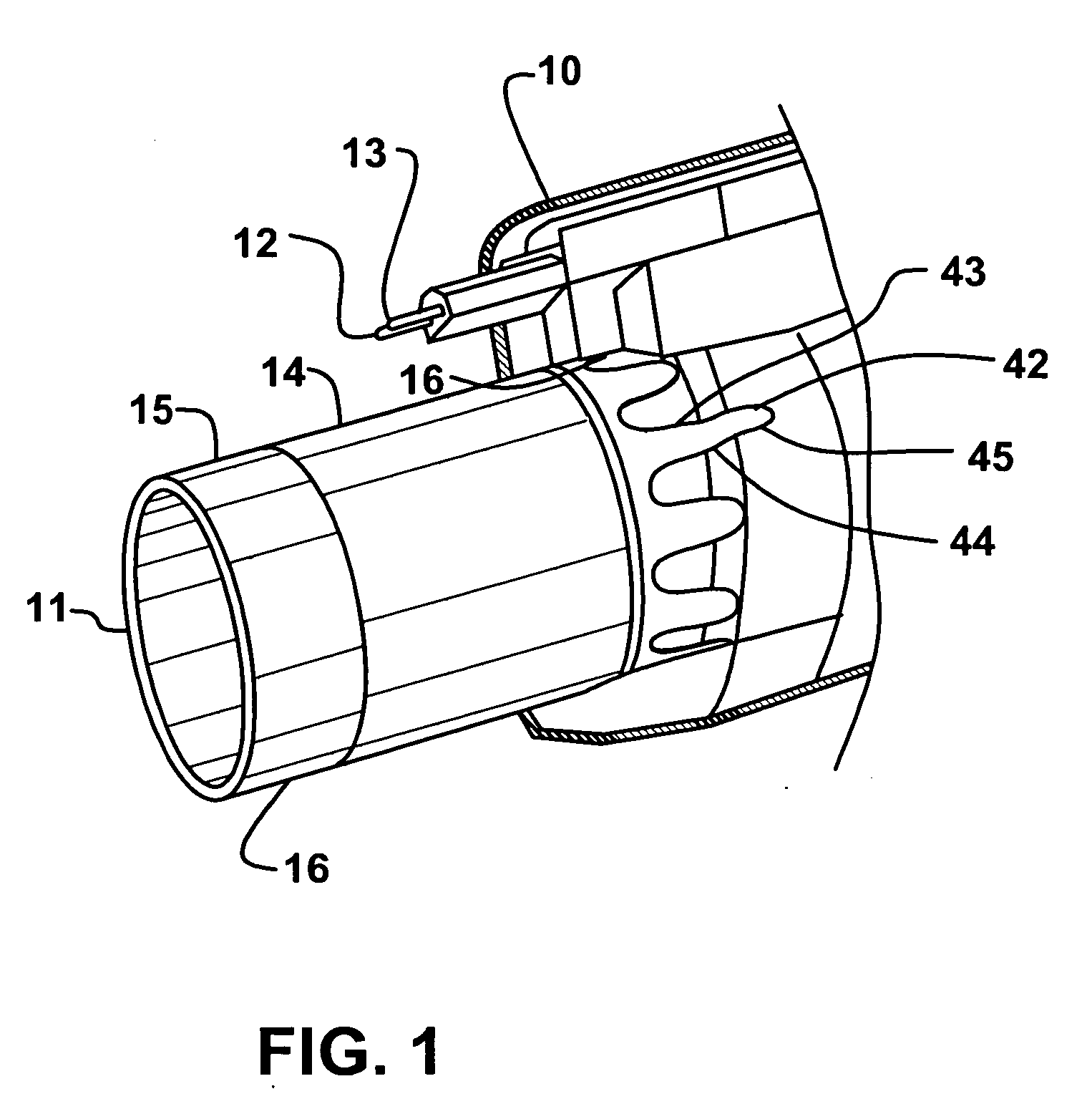
[0023]As seen in FIG. 1, there is a core 10 over which a housing 53 is secured. The core has an end fitting that is secured to an end of a hose (not shown). The core 10 has a first end that is secured to a hose and a second end 11 opposite the first end. The second end 11 of the core 10 is adapted to be inserted into an opening in the Type A wall valve or an opening in a motorized power head or other accessory. The housing 53 has a pair of high voltage connectors 12 and 13 to provide power to the power nozzle or other powered device on the opposite end of the hose from the housing 53 when the core 10 is inserted in a Type A wall outlet. In this embodiment there are a pair of pins or pigtails extending from the housing that are insertable into a pair of pin openings in the wall valve. In an alternate configuration of the wall valves there may be a direct connection instead of pigtails. They both use LV contact plates, but the supply of HV power is different. In direct connect, power ...


PUM


Abstract

An improved end fitting for a hose adapted for use with a central vacuum system is provided. The end fitting has a housing and a cylindrical member extending from the housing. The cylindrical member is adapted to be received by a wall inlet. The cylindrical member has an end portion of a first diameter and a neck of a second smaller diameter and at least one spring contact plate positioned over the neck to provide an electrical connection to the wall inlet.

Description

FIELD OF THE INVENTION [0001]The present invention is primarily directed to the field of central vacuum systems and more particularly, to an improved end fitting having a spring contact plate for providing more consistent electrical contact between an end fitting on a hose used in a central vacuum system and the respective wall inlet.BACKGROUND OF THE INVENTION [0002]While movable vacuum cleaners make up the vast majority of vacuum systems in homes and businesses, there has recently been a significant increase in the use of central vacuum cleaning systems. Movable or portable vacuum cleaners are plugged into an electric outlet and or self-contained system for picking up dust, dirt and debris. Provided there is a long enough cord, the portable vacuum can cover most areas in a home or other building without too much difficulty.[0003]The primary advantage of a central vacuum system is that the user does not have to carry a heavy unit from room to room or up and down stairs. This is par...

Claims


Application Information

Patent Timeline
Patent Type & Authority Applications(United States)
IPC IPC(8): A47L5/38
CPCA47L5/38H01R13/005A47L9/246
Inventor SMITH, STACY
Owner FLEXIBLE TECH INC
Why Eureka
Try Eureka