Bearing and shaft arrangement for electric drive unit

Active Publication Date: 2021-06-24
GM GLOBAL TECH OPERATIONS LLC
View PDF0 Cites 0 Cited by
  • Summary
  • Abstract
  • Description
  • Claims
  • Application Information

AI Technical Summary

Problems solved by technology

The use of tapered bearings therefore are accommodated by additional structure of a transmission housing, and also increase a noise, vibration harshness (NVH) of th

Method used


Image

  • Bearing and shaft arrangement for electric drive unit
  • Bearing and shaft arrangement for electric drive unit

Examples


Embodiment Construction

[0030]The following description is merely exemplary in nature and is not intended to limit the present disclosure, application, or uses.

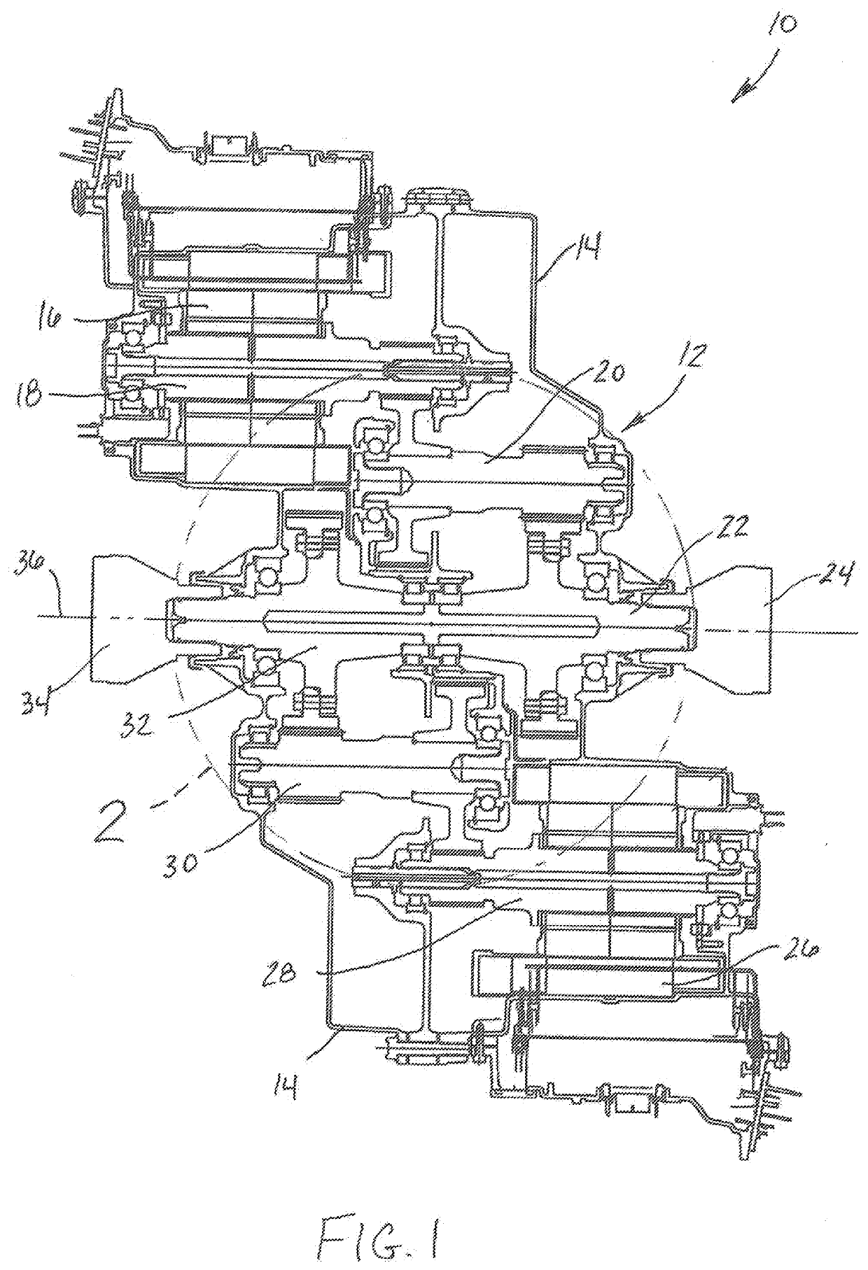
[0031]Referring to FIG. 1, a bearing and shaft arrangement 10 for an electric drive unit 12 includes a housing such as a gearbox 14 having a first electric motor 16. The first electric motor 16 engages and axially rotates a first motor shaft 18 defining rotation about a longitudinal axis of rotation of the shaft within the gearbox 14. The first motor shaft 18 is engaged with and axially rotates a first transfer shaft 20 within the gearbox 14. The first transfer shaft 20 is engaged with and axially rotates a first shaft 22 within the gearbox 14. According to several aspects the first shaft 22 defines a half-shaft. The first shaft 22 is coupled to and rotates a first wheel hub 24. Within the gearbox 14 the electric drive unit 12 also includes a second electric motor 26. The second electric motor 26 engages and axially rotates a second motor shaft 28 w...


PUM


Abstract

A bearing and shaft arrangement of an automobile vehicle electric drive unit includes a gearbox. A first electric motor within the gearbox is engaged with and axially rotates a first shaft within the gearbox. A second electric motor within the gearbox is engaged with and axially rotates a second shaft within the gearbox. A first roller bearing assembly supports the first shaft to a first structural member of the gearbox. A second roller bearing assembly supports the second shaft to the first structural member of the gearbox. A thrust bearing is positioned between the first roller bearing assembly and the second roller bearing assembly and directly contacts the first shaft and the second shaft in a drive mode and reacts a first axial load of the first shaft and a second axial load of the second shaft directed toward the first axial load.

Description

INTRODUCTION[0001]The present disclosure relates to automobile vehicle electric drive units.[0002]Automobile vehicle transmissions commonly support half shafts using tapered bearings that require preloading. Tapered bearings permit minimal axial displacement of the half shafts, however tapered bearings impart thrust and frictional loads that are reacted using structure of a transmission housing. The use of tapered bearings therefore are accommodated by additional structure of a transmission housing, and also increase a noise, vibration harshness (NVH) of the transmission.[0003]It is also common for the half-shafts to be independently positioned and supported in an off-axis configuration due to the structure and bearing designs required to carry the shaft axial and radial loads. Bearings positioned proximate to outer walls of the transmission housing increase noise output and require added structure and weight to accommodate.[0004]Thus, while current automobile vehicle electric drive...

Claims


Application Information

Patent Timeline
IPC IPC(8): B60K1/02H02K5/173H02K7/00H02K7/08H02K7/116B60K17/04F16C19/54F16C19/10
CPCB60K1/02H02K5/1735H02K7/006H02K7/085F16C2361/65B60K17/04F16C19/54F16C19/10H02K2205/03H02K7/116F16H57/023F16H57/021H02K16/00B60K17/22F16C35/063F16C2326/01F16C35/067F16C3/02
Inventor GAYNEY, JACKDENESZCZUK, GREGORYBURGMAN, BORIS
Owner GM GLOBAL TECH OPERATIONS LLC
Why Eureka
Try Eureka