Thermal processing roller and temperature control apparatus for roller

a technology of temperature control apparatus and roller, which is applied in lighting and heating apparatus, electric/magnetic/electromagnetic heating, instruments, etc., can solve the problems of inability to perform uniform thermal processing, and inability to meet the needs of heat exchanger and pump. to achieve uniform thermal processing of a member, the effect of uniform thermal processing

Active Publication Date: 2006-01-31
TOKUDEN CO LTD
View PDF9 Cites 11 Cited by
  • Summary
  • Abstract
  • Description
  • Claims
  • Application Information

AI Technical Summary

Benefits of technology

[0011]The invention has been made in view of the aforesaid problem of the conventional technique, and an object of the present invention is to provide a thermal processing roller and a temperature control apparatus for the roller which can perform uniform thermal processing of a member to be processed, miniaturize a heat exchanger and a pump, and perform uniform thermal processing of the member to be processed without enlarging the heat exchanger and the pump.
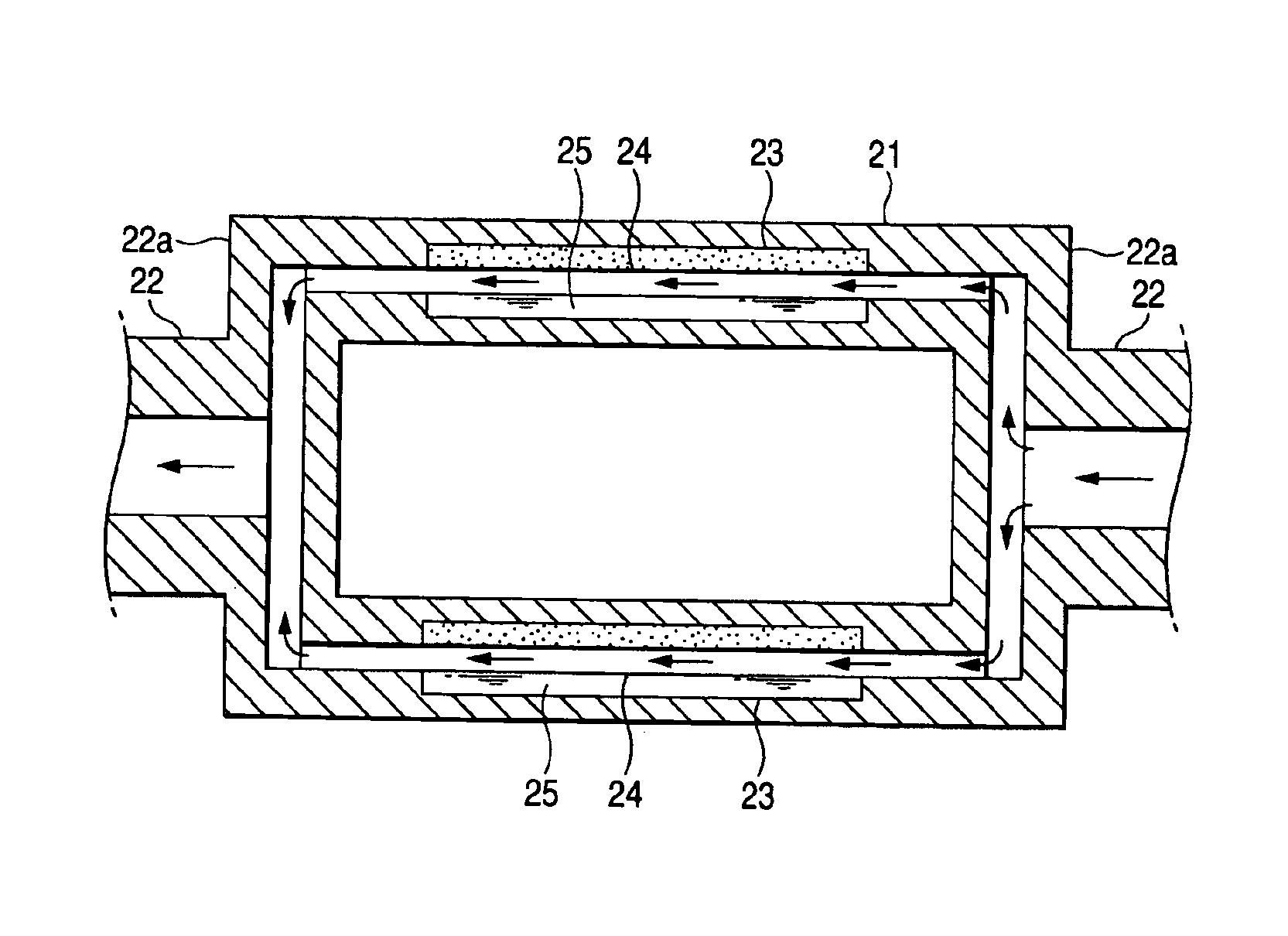
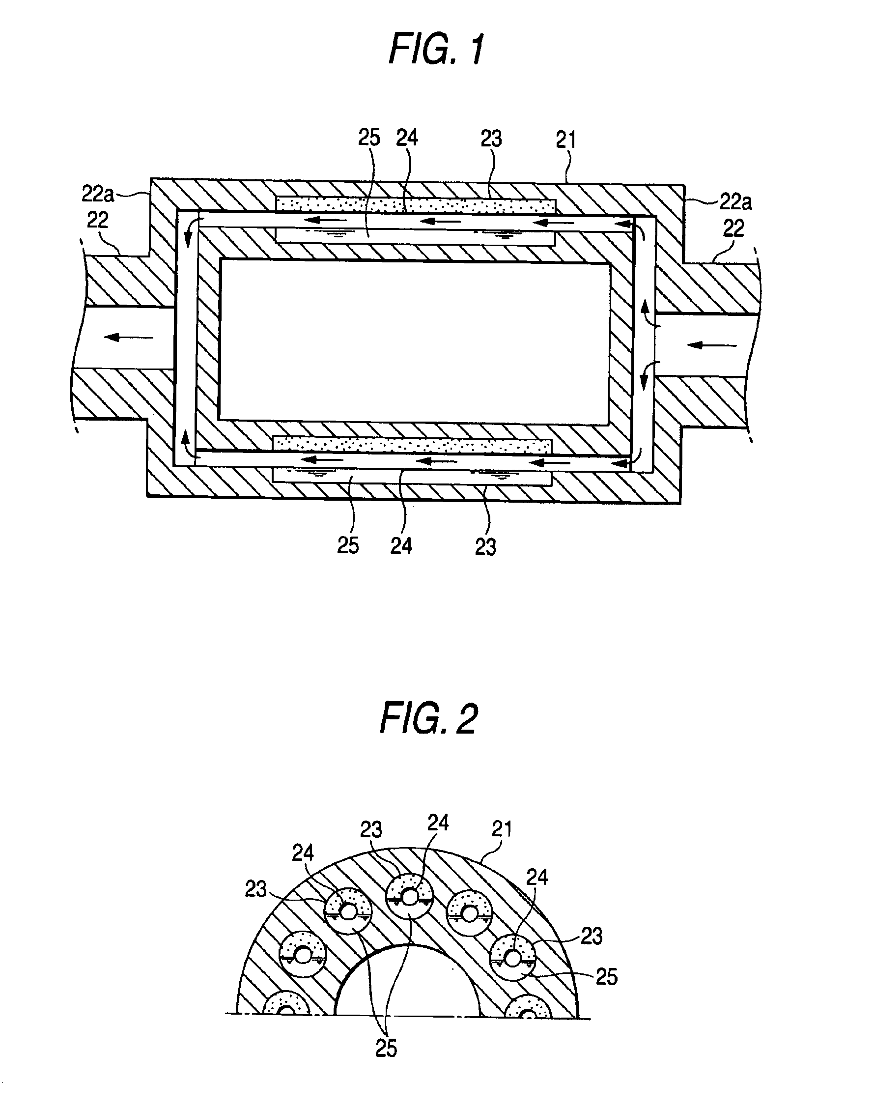
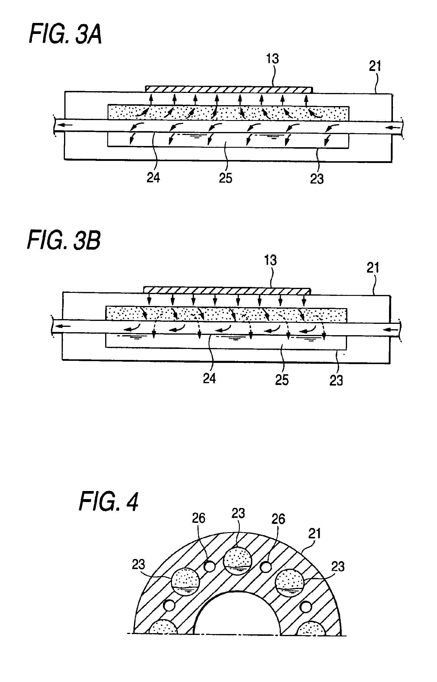
[0019]According to the thermal processing roller according to the invention, the sealed chamber extending in the longitudinal direction of the roller and in which the heat transfer medium of vapor-liquid two phases is sealed is provided within the thick portion of the roller. Thus, even if there arises a difference between the temperature of the heat transfer fluid flowing into the roller and the temperature of the heat transfer fluid flowing from the roller after heating the member to be processed or absorbing heat therefrom, due to the movement of the latent heat of the heat transfer medium of the vapor-liquid two phases, the surface temperature of the roller in the longitudinal direction along the axis core of the roller is made uniform. Thus, the uniform thermal processing can be performed as to the member to be processed abutting against the roller in the longitudinal direction along the axis core of the roller without increasing a flow rate of the heat transfer fluid. Further, when the electromagnetic induction heating mechanism is added, a response speed reaching a necessary temperature can be made faster by suitably driving the electromagnetic induction heating mechanism, for example, by driving the mechanism at the time of changing the processing temperature etc.
[0020]Further, according to the temperature control apparatus according to the invention, when the surface temperature of the roller is lower (higher in the case of heat absorption) than the predetermined range of the target value (the second setting temperature), the control is performed by the temperature control unit (the first temperature control unit) in which the temperature of the heat transfer fluid is set to a value (the first setting temperature) higher (lower in the case of heat absorption) than the target value of the surface temperature of the roller. In contrast, when the surface temperature of the roller is within the predetermined range of the target value (the second setting temperature), the control is performed by the temperature control unit (the second temperature control unit) in which the temperature of the heat transfer fluid is set to the target value (the second setting temperature) of the surface temperature of the roller. Thus, at the initial stage where the surface temperature of the roller is quite smaller as compared with the target value, the surface temperature of the roller can be raised rapidly near the target value.
[0021]After the surface temperature of the roller reaches the target value, when the member to be processed passes through the surface of the roller, the surface temperature of the roller reduces (increases in the case of heat absorption). When the reduction exceeds the predetermined range of the target value of the surface temperature of the roller, for example, 10% (suitably changed) of the target value, the control is performed by the temperature control unit (the first temperature control unit) in which the temperature of the heat transfer fluid is set to a value (the first setting temperature) higher (lower in the case of heat absorption) than the target value of the surface temperature of the roller. Thus, the surface temperature of the roller is almost kept to the target value, and so the uniform thermal processing of the member to be processed can be performed without enlarging the heat exchanger and the pump.
[0022]In this case, when the second temperature sensor for detecting the surface temperature of the thermal processing roller is inserted within the thick portion of the roller near the surface of the roller, the surface temperature of the roller can be detected accurately and stably and the interference between the temperature sensor and the member to be processed can be prevented. Further, since the heat transfer medium of vapor-liquid two phases is sealed into the sealed chamber formed along the longitudinal direction of the roller, even if there is a temperature difference in the heat transfer fluid between the fluid inlet and the fluid outlet, the surface temperature of the roller is kept at the uniform value due to the movement of the latent heat of the heat transfer medium. Thus, the uniform thermal processing can be performed in the width direction (the longitudinal direction of the roller) of the member to be processed passing through the surface of the roller. Further, since the surface of the roller is uniform, the surface temperature of the roller can be detected easily.

Problems solved by technology

The temperature difference appears on the surface of the roller, so that there arises a problem that the thermal processing can not be performed uniformly as to the member to be processed abutting against the surface of the roller, in the longitudinal direction of the member to be processed along the axis core of the roller.
Thus, there arises a problem that the heat exchanger for heating or cooling and the pump become inevitably larger.
As a result, there arises a problem that the heat exchanger and the pump are required to be larger.

Method used


Image

  • Thermal processing roller and temperature control apparatus for roller
  • Thermal processing roller and temperature control apparatus for roller
  • Thermal processing roller and temperature control apparatus for roller

Examples


Embodiment Construction

[0036]The embodiments of the invention will be explained with reference to the accompanying drawings. FIG. 1 is a longitudinal sectional diagram of a thermal processing roller according to an embodiment, FIG. 2 is a transversal sectional diagram showing a part thereof, and FIG. 3 is diagrams for explaining the operation thereof, in which FIG. 3A and FIG. 3B are diagrams for explaining the operations at the time of heating and heat-absorbing, respectively. The circulation path of the heat transfer fluid formed by the rotary joint 4, the oil storage tank 5, the heat exchanger 7 for heating or cooling, the temperature sensor 9 and the pump 8 shown in FIG. 12 is abbreviated in the drawings.

[0037]In FIGS. 1 to 3, 13 depicts a member to be processed such as a resin film, 21 a roll shell, 22 a rotation driving shaft, 23 a sealed chamber, 24 a heat transfer medium flowing tube and 25 heat transfer medium forming vapor-liquid two phases.

[0038]The roll shell 21 is configured in a cylindrical ...


PUM

PropertyMeasurementUnit
temperatureaaaaaaaaaa

Abstract

A thermal processing roller includes a heat transfer medium flowing path therein and heats a member to be processed abutting against a surface of the roller or absorbs heat therefrom by heat transfer fluid flowing through the heat transfer medium flowing path, wherein a sealed chamber extending in a longitudinal direction of the roller and in which heat transfer medium of vapor-liquid two phases is sealed is formed within a thick portion of the roller.

Description

BACKGROUND OF THE INVENTION[0001]1. Field of the Invention[0002]The present invention relates to a thermal processing roller for subjecting a member to be processed such as a resin film to a heating processing or a heat-absorbing processing by using fluid as heat transfer medium, and relates to a temperature control apparatus for the roller.[0003]2. Description of the Related Art[0004]In general, when a member to be processed such as a resin film is applied to a roller, the member is heated to a predetermined temperature or the member at a high temperature is cooled to a predetermined temperature while the member is abutted against and passes through the roller. In the case of performing the heating processing, the roller is heated to a temperature necessary for the heating processing. In contrast, in the case of performing the heat-absorbing processing, since the temperature of the roller itself increases due to heat absorbed from the member to be processed, the roller is cooled to...

Claims


Application Information

Patent Timeline
Patent Type & Authority Patents(United States)
IPC IPC(8): H05B6/14F28D15/02F28F5/02
CPCF28F5/02F28D15/02
Inventor KITANO, YOSHIOTONOMURA, TORUOKAMOTO, KOZOHIROTA, SHIGEYUKIHEGURI, MASANOBUHANAFUSA, TOSHIKI
Owner TOKUDEN CO LTD
Why Eureka
Try Eureka