Shielded surface mount coaxial connector

a coaxial connector and shielded surface technology, applied in the field of shielded surface mount coaxial connectors, can solve the problems of signal reflection can and often do interfere with the performance of a device, and the discontinuity of the signal path, so as to reduce spurious electromagnetic radiation and reduce the discontinuity of impedan

Inactive Publication Date: 2006-01-31
AGILENT TECH INC
View PDF12 Cites 35 Cited by
  • Summary
  • Abstract
  • Description
  • Claims
  • Application Information

AI Technical Summary

Benefits of technology

[0011]In other aspects of the present invention, a system for removably connecting to an RF or microwave device is provided. The system comprises the surface mountable coaxial connector of the present invention, and further comprises a multilayer planar circuit and a mounting footprint on an exposed surface of the multilayer planar circuit that is adapted to accept the coaxial connector. Moreover, a method of interfacing a coaxial connector to a printed circuit board is provided. The method comprises electromagnetically shielding a coaxial transmission line at an interface created between a coaxial connector and a printed circuit board when the connector is attached to the printed circuit board. The method furt

Problems solved by technology

Unfortunately, the presence of the gap 30 results in a signal path discontinuity experienced by a signal traveling between the connector 10 and the transmiss

Method used


Image

  • Shielded surface mount coaxial connector
  • Shielded surface mount coaxial connector
  • Shielded surface mount coaxial connector

Examples


Embodiment Construction

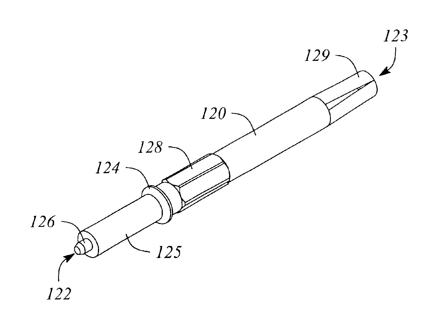
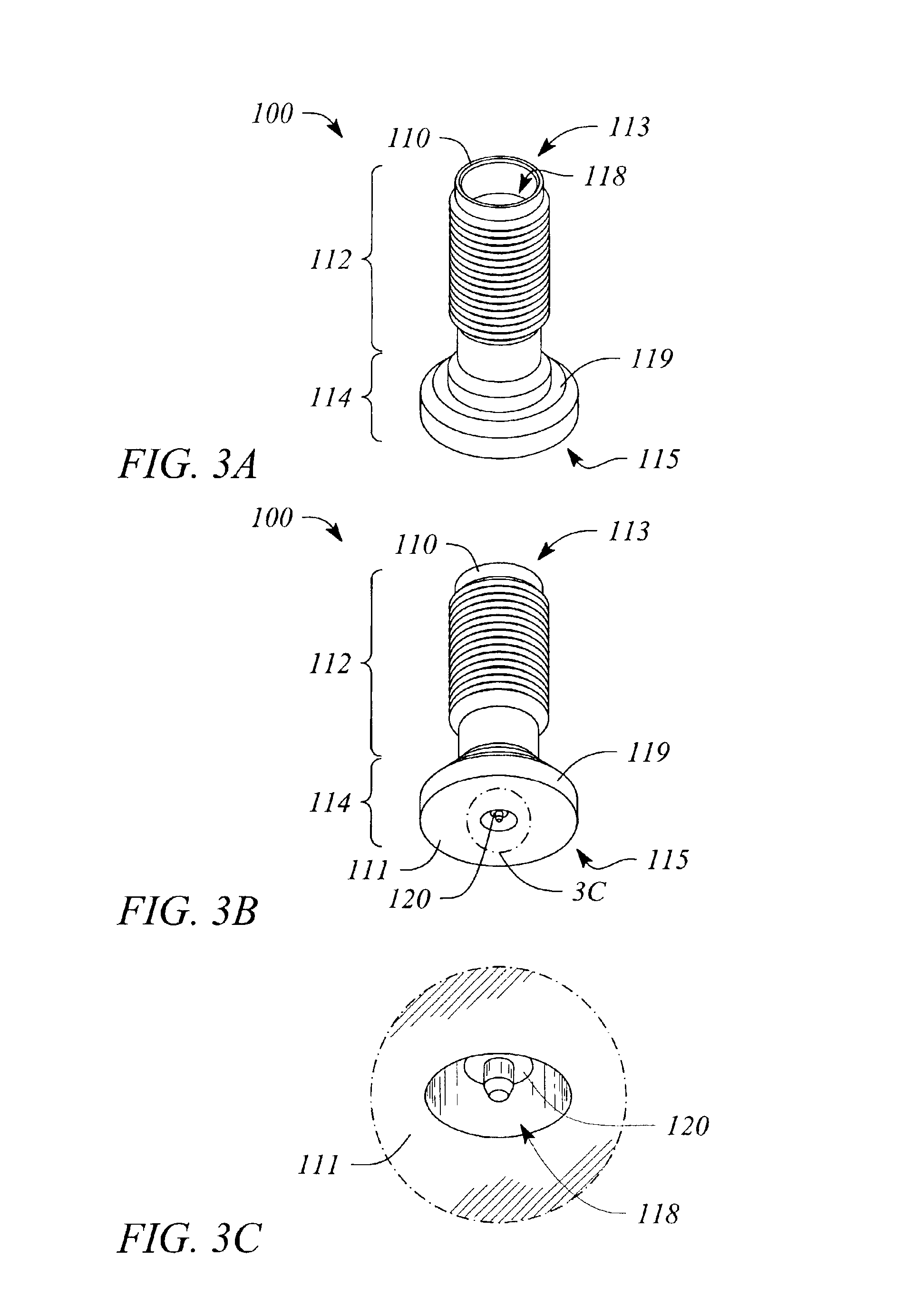
[0030]FIG. 3A illustrates a perspective end view of a shielded, surface-mountable (SMT) coaxial connector 100 according to an embodiment of the present invention. The end view illustrated inFIG. 3A is referred to as ‘top-oriented’ herein also. FIG. 3B illustrates a perspective end view of the shielded (SMT) coaxial connector 100 embodiment illustrated in FIG. 3A from an opposite end of the connector 100. The opposite end view illustrated in FIG. 3B is referred to as ‘bottom-oriented’ herein also. FIG. 3C illustrates a magnified view of a portion of the end view illustrated in FIG. 3B that is within a dashed circle labeled 3C. The view illustrated in FIG. 3C is of a surface 111 of the opposite end of the shielded SMT connector 100. The portion of the surface 111 illustrated in FIG. 3C includes an exit end of a coaxial transmission line of the connector 100. FIG. 4 illustrates a cross-sectional view of an embodiment of the shielded SMT coaxial connector 100 according to the present in...


PUM


Abstract

A coaxial connection is electromagnetically shielded at an interface between a surface mountable coaxial connector and a planar circuit operating in the radio frequency (RF) and microwave frequency ranges. In addition or alternatively, the coaxial connection reduces a potential impedance mismatch associated with attaching a coaxial transmission line of the coaxial connector to a planar transmission line of the planar circuit.

Description

TECHNICAL FIELD[0001]The invention relates to radio frequency (RF) and microwave circuits and systems. In particular, the invention relates to coaxial connectors used with planar circuits operating at RF and microwave frequencies.BACKGROUND ART[0002]High frequency devices, circuits and subsystems, such as those operating at radio frequency (RF) and microwave frequency ranges, are often manufactured as or using a planar circuit. The planar circuits, typically referred to as ‘printed circuit boards’ (PCBs), frequently are interconnected with one another using coaxial cables. Coaxial connectors at an interface between a PCB and the coaxial cable enable the individual PCB to be connected and disconnected during assembly and / or test, as well as for maintenance and replacement purposes once the PCB has been deployed. A variety of classes or series of standard and semi-custom coaxial connectors are readily available and in widespread use including, but not limited to, SMA, SMB, SMC, SSMA, ...

Claims


Application Information

Patent Timeline
IPC IPC(8): H01P1/04H01P5/02H01P5/08
CPCH01P5/085
Inventor BARNES, HEIDI L.SMITH, ANDREW N.BISHOP, FLOYD A.
Owner AGILENT TECH INC
Why Eureka
Try Eureka