
Optical module

A technology of optical modules and optical transmitting sub-modules, which is applied in the field of optical modules and can solve problems such as signal integrity degradation and impedance discontinuity

Pending Publication Date: 2021-08-31
HISENSE BROADBAND MULTIMEDIA TECH
View PDF8 Cites 2 Cited by
  • Summary
  • Abstract
  • Description
  • Claims
  • Application Information

AI Technical Summary

Problems solved by technology

[0004] The embodiment of the present application provides an optical module to solve the problem that there is an impedance discontinuity at the soldering point between the airtight housing pad of the optical module and the flexible circuit board pad, resulting in poor signal integrity.

Method used


Image

  • Optical module
  • Optical module
  • Optical module

Examples


Embodiment Construction

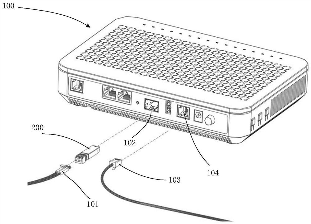
[0023] The following will clearly and completely describe the technical solutions in the embodiments of the application with reference to the drawings in the embodiments of the application. Apparently, the described embodiments are only some of the embodiments of the application, not all of them. Based on the embodiments in this application, all other embodiments obtained by persons of ordinary skill in the art without creative efforts fall within the protection scope of this application.

[0024] One of the core links of optical fiber communication is the mutual conversion of optical and electrical signals. Optical fiber communication uses optical signals carrying information to be transmitted in information transmission equipment such as optical fibers / optical waveguides, and the passive transmission characteristics of light in optical fibers / optical waveguides can be used to achieve low-cost, low-loss information transmission; and information processing equipment such as com...


PUM


Abstract

The invention provides an optical module comprising a circuit board, a light emitting sub-module and a flexible circuit board; the light emitting sub-module comprises a shell and a ceramic switching block plated with a metal layer, one side of the ceramic switching block is inserted into the shell, and the other side of the ceramic switching block is exposed outside the shell; signal and grounding bonding pads are arranged on the metal layer of the ceramic switching block, and the signal bonding pads on the inner side and the outer side of the ceramic switching block are connected; an isolation groove is formed between the signal bonding pad and the grounding bonding pad located on the outer side of the shell and on the ceramic switching block, and the isolation groove is sunken in the signal bonding pad and the grounding bonding pad; and one end of the flexible circuit board is connected with the ceramic switching block, and the other end of the flexible circuit board is connected with the circuit board. The isolation groove is formed between the signal bonding pad and the grounding bonding pad, exposed on the outer side of the shell, on the ceramic switching block, the isolation groove is sunken in the signal bonding pad, the dielectric constant of the ceramic switching block is reduced through the isolation groove, impedance discontinuous points at the connecting position of the flexible circuit board and the ceramic switching block are reduced, and thus the signal transmission quality is improved, and the signal integrity is ensured.

Description

technical field [0001] The present application relates to the technical field of optical fiber communication, and in particular to an optical module. Background technique [0002] With the development of cloud computing, mobile Internet, video and other new business and application models, the development and progress of optical communication technology has become more and more important. In optical communication technology, the optical module is a tool to realize the mutual conversion of photoelectric signals, and it is one of the key components in optical communication equipment. With the development of optical communication technology, the transmission rate of optical modules continues to increase. [0003] An optical module usually includes a circuit board and an optical sub-module, and the optical sub-module can be hermetically sealed or non-hermeticly packaged. In high-speed products, the optical sub-module is usually hermetically packaged, and the airtight housing an...

Claims


Application Information

Patent Timeline
IPC IPC(8): G02B6/42
CPCG02B6/4281G02B6/4274G02B6/428G02B6/4251
Inventor 张加傲王欣南慕建伟
Owner HISENSE BROADBAND MULTIMEDIA TECH
Learn More