
Exposure apparatus and method

a technology of exposure apparatus and apparatus, applied in the field of exposure methods and apparatuses, can solve the problems of reducing contrast, reducing contrast, and affecting imaging performance, so as to prevent deterioration of imaging performance and maintain desired contrast.

Inactive Publication Date: 2006-01-31
CANON KK
View PDF5 Cites 36 Cited by
  • Summary
  • Abstract
  • Description
  • Claims
  • Application Information

AI Technical Summary

Benefits of technology

[0021]Accordingly, it is an exemplified object of the present invention to provide an immersion type exposure method and apparatus which prevent deteriorated imaging performance due to influence of polarization, maintain desired contrast, and form desired patterns.

Problems solved by technology

The influence of polarization on the imaging performance is serious because two beams that form the basic frequency have large angles.
Moreover, in the immersion case, two-beam imaging can problematically meet a condition in that no image is formed at all in a certain polarized light direction.
The p-polized light does not contribute to the imaging, thus halving the contrast, and creating a reduced contrast problem.
This problem is inevitable since an optical system for immersion is required to have super-high NA, which means much larger than 1.0.

Method used


Image

  • Exposure apparatus and method
  • Exposure apparatus and method
  • Exposure apparatus and method

Examples


example 1

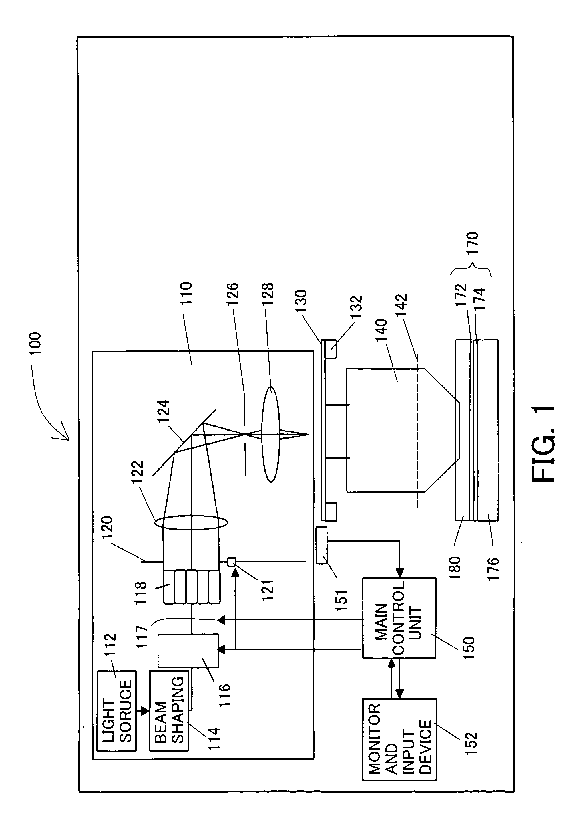
[0109]A description will be given of an example 1 according to the present invention utilizing the immersion type exposure apparatus 100. The exposure apparatus 100 uses ArF excimer laser (with a wavelength of 193 nm) as the light source 112, and projection optical system 140 having a numerical aperture of 1.32, wherein the largest angle θNA in the liquid 180 meets sin θNA=0.9, the liquid 180 has a refractive index of 1.47, and the illumination system meets σMAX=0.9. The projection exposure apparatus is a reduction projection exposure. While a target pattern size and a mask pattern size are different according to the reduction ratio of the exposure apparatus. The following description converts a pattern size on the mask 130 into a size on the wafer 170.

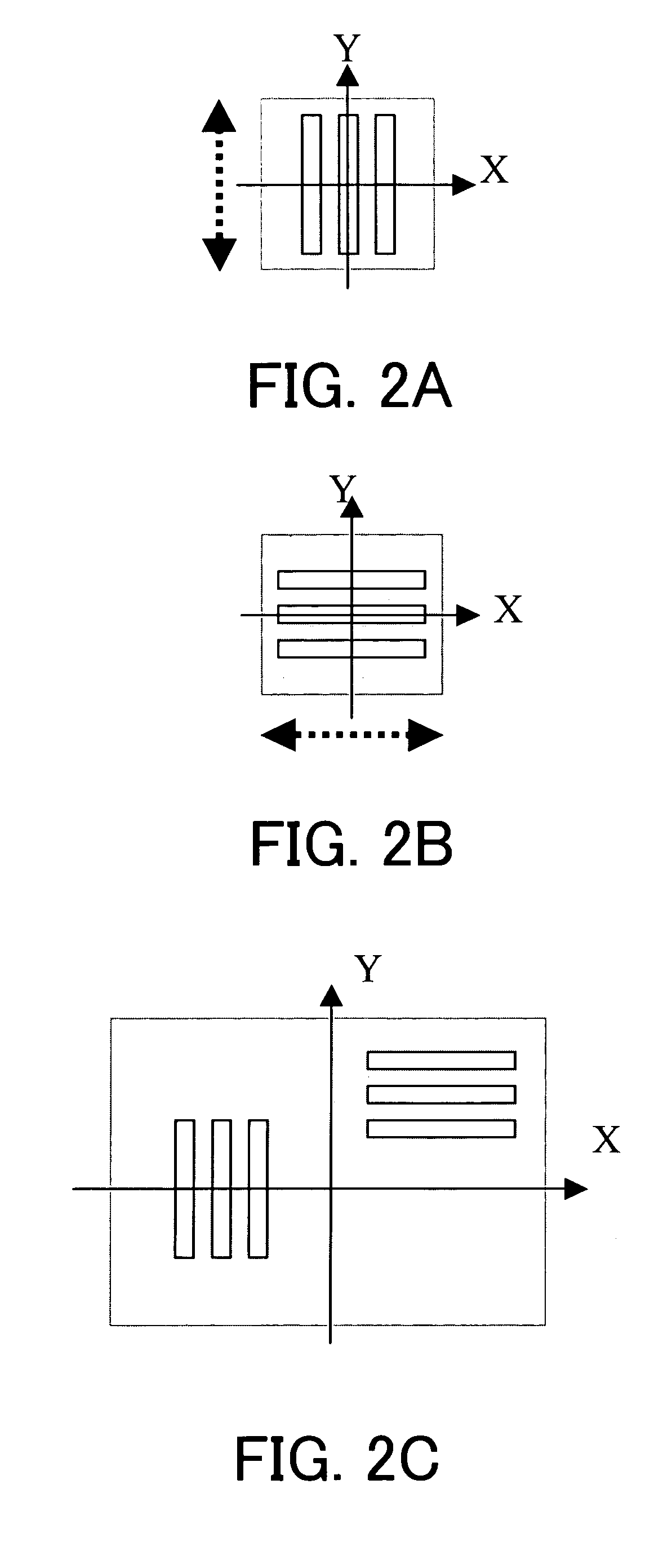
[0110]FIGS. 11A and 11B show contrast depths (μm) while varying critical dimensions and intervals, or pitches, in the mask pattern shown in FIG. 2C which mixes line-and-space (“L / S”) patterns that have an equal critical dimension and ...

example 2

[0114]A description will be given of an example 2 according to the present invention utilizing the immersion type exposure apparatus. Similar to the example 1, this exposure apparatus uses ArF excimer laser (with a wavelength of 193 nm) as the light source 112, and projection optical system 140 having a numerical aperture of 1.32, wherein the largest angle θNA in the liquid 180 meets sin θNA=0.9, the liquid 180 has a refractive index of 1.47, and the illumination system has σMAX=0.9.

[0115]FIGS. 12A and 12B show contrast depths of focus (μm) while varying critical dimensions and intervals, or pitches, in the unidirectional mask pattern shown in FIG. 2A which includes L / S patterns that have an equal critical dimension and interval, and extend parallel to the Y directions.

[0116]When sin θNA=0.9, θNA was 64°. sin(90−θNA) / sin θNA=0.44 / 0.9=0.49. Since a value of a corresponding to a region upon which only the s-polarized light is incident along the axis parallel to the pattern direction s...


PUM

PropertyMeasurementUnit
wavelengthaaaaaaaaaa

Abstract

An exposure method immerses, in liquid, a surface of an object to be exposed, and a surface of a projection optical system closest to the object, and projects a repetitive pattern formed on a mask via the projection optical system onto the object. The exposure method forms on a pupil of the projection optical system an effective light source that emits, from an axis orthogonal to an optical axis of the projection optical system, light that is parallel to a repetitive direction of the repetitive pattern and has an incident angle θ upon the object, wherein the light includes only s-polarized light in an area of an incident angle θ that satisfies 90°−θNA≦θ≦θNA, where θNA is the largest value of the incident angle θ.

Description

[0001]This application claims a benefit of priority based on Japanese Patent Application No. 2002-358764, filed on Dec. 10, 2002, which is hereby incorporated by reference herein in its entirety as if fully set forth herein.BACKGROUND OF THE INVENTION[0002]The present invention relates generally to an exposure method and apparatus used to fabricate various devices including semiconductor chips such as ICs and LSIs, display devices such as liquid crystal panels, sensing devices such as magnetic heads, and image pick-up devices such as CCDs, as well as fine contact hole patterns used for micromechanics, and more particularly to a so-called immersion type exposure method and apparatus that immerse, in liquid, a surface of an object to be exposed, and a bottom surface of a projection optical system closest to the object, and expose an object via the liquid.[0003]Reduction projection exposure apparatus has been conventionally employed which use a projection optical system for projecting ...

Claims


Application Information

Patent Timeline
Patent Type & Authority Patents(United States)
IPC IPC(8): G03B27/52G03B27/72G03B27/42H01L21/027G03F7/20
CPCG03F7/70091G03F7/70125G03F7/70958G03F7/70341G03F7/70566G03F7/7025H01L21/027
Inventor KAWASHIMA, MIYOKOSUZUKI, AKIYOSHI
Owner CANON KK
Learn More