Wave transformation method and device

a wave transformation and high-voltage switch technology, applied in power conversion systems, ac-ac conversion, electrical equipment, etc., can solve the problems of heavy harmonic wave pollution of electric network and electric devices, increase equipment costs, and reduce equipment working efficiency, so as to improve working efficiency, reduce costs, and simplify circuits

Inactive Publication Date: 2006-01-31
BEIJING RESTIME ELECTRICAL TECH
View PDF5 Cites 21 Cited by
  • Summary
  • Abstract
  • Description
  • Claims
  • Application Information

AI Technical Summary

Benefits of technology

[0003]The object of the present invention is to provide a wave transformation method and device which eliminate the intermediate DC stage in order to reduce the cost of the device and improve working efficiency, and it is still a further object of the preset invention to provide a wave transformation method and device to delivers smaller voltage harmonics and higher power factor.
[0020]The wave transformation method and device of present invention eliminates the intermediate DC stage, so the circuit is greatly simplified, therefore it can reduce the cost and improve working efficiency, deliver smaller voltage and current harmonics and higher power factor.

Problems solved by technology

Such a solution achieves a relative low power factor and may result in heavy harmonic wave pollution to the electric network and electric devices.
Such a solution increases equipment cost and decreases working efficiency of equipment due to existence of the intermediate DC stage.
Above problems are more severe in high capacity frequency converters and variable-frequency power supplies.

Method used


Image

  • Wave transformation method and device
  • Wave transformation method and device
  • Wave transformation method and device

Examples


Embodiment Construction

[0003]The object of the present invention is to provide a wave transformation method and device which eliminate the intermediate DC stage in order to reduce the cost of the device and improve working efficiency, and it is still a further object of the preset invention to provide a wave transformation method and device to delivers smaller voltage harmonics and higher power factor.

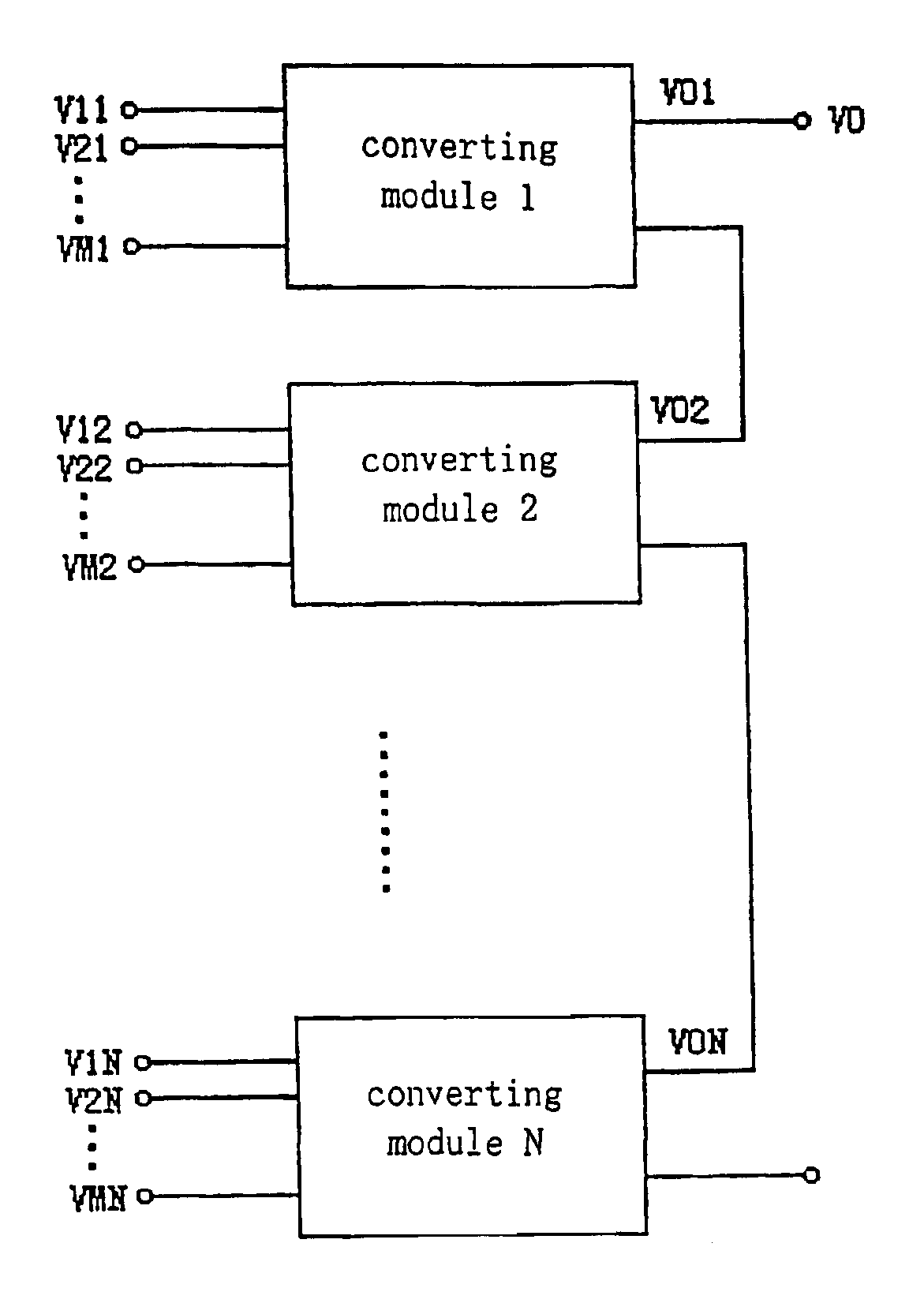
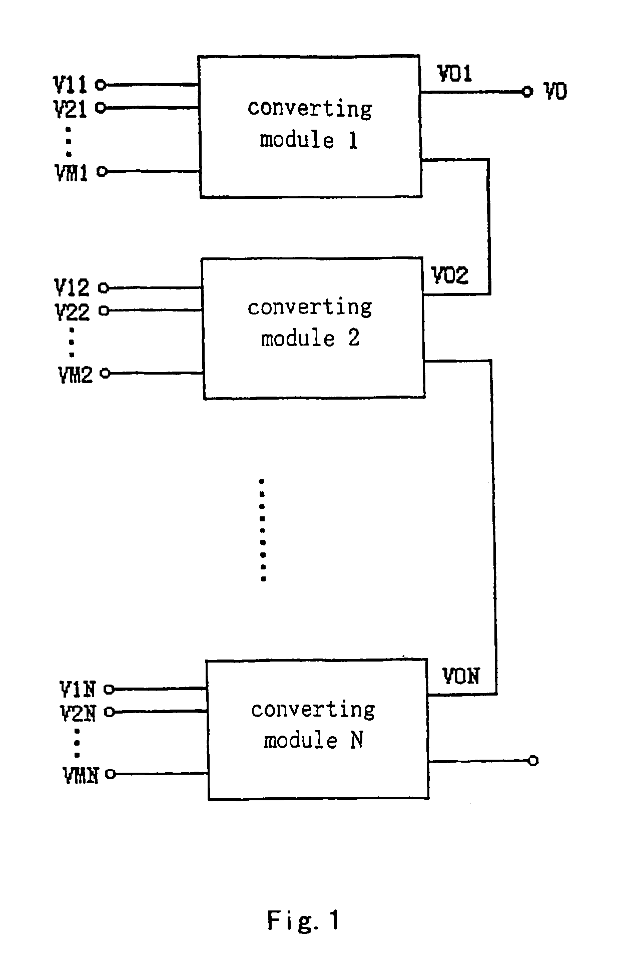
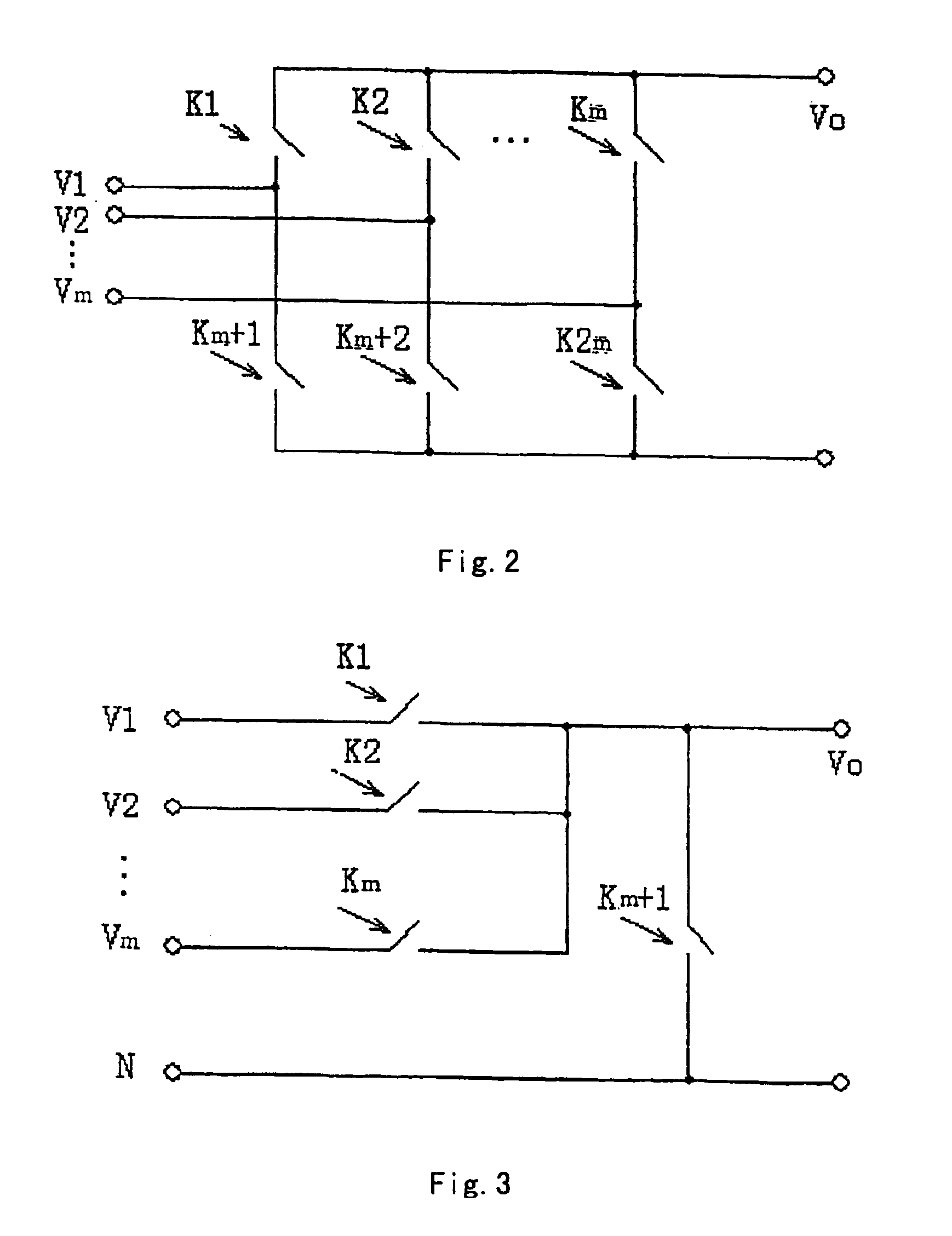
[0004]The AC-AC wave transformation device in the present invention comprises n transformation modules. The input terminals of those transformation modules are connected to n groups of electrical insulating AC. Each group has m phases. The output ends of those transformation modules are connected in series to form a total voltage output. Each of those transformation modules further comprises power semiconductor switch components or power semiconductor switch component groups to form a bi-directionally controllable m-phases rectification circuit, the output polarity of which is variable.

[0005]The transformati...


PUM


Abstract

The present invention relates a waveform transformation method and apparatus. It uses multilevel transformation module in series, and the output voltages of power modules at all levels are superposed to get the total output voltage, whereas each power transformation module realizes AC-to-AC direct conversion. The deviation between the output′ voltage and setting reference voltage at any time point is made as small as possible by selecting different transformation modules as current working circuit and selecting output voltage waveform of the each different transformation modules. The invention includes outputting n groups of electrical insulating AC and n transfonnation modules connected with AC. The wave transformation method and device of present invention eliminates the intermediate DC stage, so that the circuit is greatly simplified, the cost is reduced obviously and improve working efficiency. It makes voltage and current harmonics to be reduced and obtains higher power factor.

Description

FIELD OF INVENTION[0001]The present invention is related to a wave transformation method and device in high voltage switch field. More particularly, this invention is related to a variable-frequency drive or variable-frequency power supply for motors.BACKGROUND OF INVENTION[0002]Frequency converters and variable-frequency power supplies are widely used as driving units for AC (alternating current) motors and so on, and most of them employ AC-AC conversion or AC-DC (direct current) conversion mode. The existing technology for AC-AC frequency converters utilizes direct AC-AC conversion and output Volt Alternating Current (VAC) through altering the triggering angle of a switch component. Such a solution achieves a relative low power factor and may result in heavy harmonic wave pollution to the electric network and electric devices. On the other hand, the existing technology for voltage-type AC-DC-AC general-purpose frequency converters employs pulse-width modulation (PWM) method (i.e.,...

Claims


Application Information

Patent Timeline
Patent Type & Authority Patents(United States)
IPC IPC(8): H02M5/00H02M5/257H02M5/02H02M5/22H02M5/27H02M7/00
CPCH02M5/22H02M5/271H02M2001/0077H02M1/0077
Inventor ZHANG, DONGSHENG
Owner BEIJING RESTIME ELECTRICAL TECH
Why Eureka
Try Eureka